


Extreme Series 10.1" Monitor/DVR System
© 2022 McNeilus Truck and Manufacturing, Inc.
8
Installation
Basic Installation for Monitor 10.1" and its Components
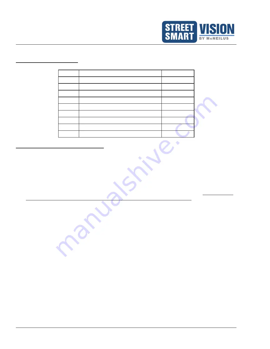
Monitor 10.1" Kit Parts List
Item
Description
Quantity
1
10.1” LCD Monitor (PN 1654644)
1
2
Sun Shield
1
3
Mounting Bracket
1
4
Screws
4
5
Remote Control
1
6
Power Accessory Harness
1
7
Camera Harness
1
8
SD Card Lock Cover (with 2 screws)
1
9
GPS Antenna
1
Monitor and GPS Receiver Installation
READ AND UNDERSTAND THESE INSTALLATION INSTRUCTIONS BEFORE INSTALLING THE
MONITOR AND CABLES.
Follow all Lockout/Tagout instructions during installation of the monitor and its equipment.
Install the monitor in the vehicle's cab, either overhead or on the dashboard, and within three feet of the driver.
(For a dual drive vehicle, the monitor must be mounted where it is accessible from both the left side and right
side driving positions.)
1. In the cab, located an area that best accommodates the monitor and the driver's view of it.
Make sure the
monitor will not obstruct any part of the driver's view for driving and operation.
It is recommended
to place the monitor on a metal surface, or in cases where the surface is plastic, support plates may be
required.
2.
Use the provided mounting bracket as a template for drilling the holes that hold the monitor in place. Verify
the area around and underneath being drilled into is clear of all wires or other items. Drill the holes.
NOTE:
If the provided bracket does not allow for positioning the monitor in the best location for the driver's view,
other bracket options are available through
McNeilus Parts at 888-686-7278 or
www.streetsmartparts.com
. If you require a different bracket for the monitor, use that bracket as a
template for drilling the holes.
NOTE:
McNeilus offers various monitor mounting hardware (RAM
®
Mount products) for purchase (see Page
16). When using this system, it is recommended to use Blue #2 Loctite on the bolts to attach the RAM
Mount ball to the back of the monitor.
3. Mount the bracket using the vibration pad with the appropriate hardware. The vibration pad is placed
between the mounting surface and the monitor mounting bracket. Hardware is not provided.
4. Before placing the monitor on the bracket, locate the four wires on the monitor from the Power Accessory
Harness: Power (red), Reverse (green), Ground (black), Battery or constant power source (yellow).
See
for more information on connecting these wires.
a. Connect the ground wire (black) to a solid chassis ground.
b. Connect the power wire (red) to an ignition power source.
c. Connect the battery wire (yellow) to constant power source or to the battery.
d. Connect the reverse wire (green) to the reverse light circuit. When connected properly, this wire allows


