background image

18

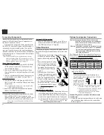
5. Rotate the PROFILE Control until the character 

“Y” appears. Refer to figure 8.

6. Repeat steps 3 thru 5 until the new name of “MY-

PHONE” is indicated on the Front Panel Display. 

Refer to figures 9 thru 11.

7. To save the new Input Name press and hold the 

VOLUME Control until the word SAVED appears 

momentarily on the Front Panel Display. Refer to 

figure 12.

The MXA70 Default Input Names (UNBAL, BAL-

ANCED, OPTICAL, COAX and AES/EBU as indi-

cated on the Front Panel Display) can be customized 

with a different name up to eight characters long (My 

Phone, MCD550, etc.). The available characters for 

renaming the input include the following:  ! < > * , / - 

_ 0 1 2 3 4 5 6 7 8 9 a b c d e f g h i j k l m n o p q r s t 

u v w x y z A B C D E F G H I J K L M N O P Q R S 

T U V W X Y Z .

In the following example, the UNBAL Input will be 

renamed to “MY-PHONE”.

1. Press and hold the INPUT CONTROL until the 

Front Panel Display indicates the Model, Firmware 

Version and Serial Number. Refer to figure 2. Then 

rotate the INPUT CONTROL and select the Setup 

Menu item “INPUT: UNBAL,  NAME: UNBAL”. 

Refer to figure 4.

Note: If the UNBAL Input is not displayed, press the 

VOLUME Control repeatedly until it is dis-

played.

2. Press and hold in the VOLUME Control until the 

character “U” of the “NAME: UNBAL” starts 

flashing. Refer to figure 5.

3. Rotate the PROFILE Control until the character 

“M” appears. Refer to figure 6.

4. Rotate the OUTPUT Control until the character 

“N” of the “NAME: UNBAL” starts flashing. 

Refer to figure 7.

The MXA70 functionality is controlled by internal 

software that is known as Firmware. The MXA70 

has two different Firmwares, one is the “System 

Firmware” (responsible for the basic operation of the 

MXA70) and the other known as USB Audio Firm

-

ware (responsible for the “USB Connection and Con-

version” of a Digital Audio Signal from the Comput-

er). The Version of the Firmwares in the MXA70 can 

be identified at any time by utilizing the Setup Mode.

1. Press and hold the INPUT CONTROL until the 

Front Panel Display indicates “MXA70  V_.__, 

S/N: _______”. The number after the “V” is the 

firmware version and the number after the “S/N” 

is the serial number of the unit. Refer to figure 2. 

2. Rotate the INPUT CONTROL Clockwise until the 

Front Panel Display indicates “MLI USB AUDIO, 

V_ . _ _. The number after the “V” is the USB 

Audio Firmware version”. Refer to figure 3.

3. To exit from the Setup Mode, press the INPUT 

CONTROL and the Front Panel Display will revert 

back to its normal display.

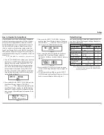
Firmware Version

Input Renaming

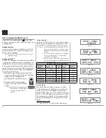
Figure 3

 MLI USB Audio

     V_.__

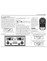
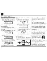
Figure 4

INPUT:  UNBAL


NAME:  UNBAL

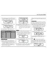
Figure 10

INPUT:  UNBAL


NAME:  MY-PL

Figure 11

INPUT:  UNBAL


NAME:  MY-PHONE

Figure 12

INPUT:  UNBAL


NAME:  SAVED

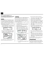
Figure 6

INPUT:  UNBAL


NAME:  MNBAL

Figure 8

INPUT:  UNBAL


NAME:  MYBAL

Figure 9

INPUT:  UNBAL


NAME:  MY-AL

Figure 5

INPUT:  UNBAL


NAME:  UNBAL

Figure 7

INPUT:  UNBAL


NAME:  MNBAL

Figure 2

  MXA70  V_.__

  S/N: _______

Summary of Contents for MXA70

Page 1: ...McIntosh Laboratory Inc 2 Chambers Street Binghamton New York 13903 2699 Phone 607 723 3512 www mcintoshlabs com MXA70 Integrated Audio System Owner s Manual...

Page 2: ...d for your safety If the provided plug does not fit into your outlet consult an electrician for replacement of the obsolete outlet 10 Protect the power cord from being walked on or pinched particularl...

Page 3: ...for you to record that information Serial Number ________________________________ Purchase Date ________________________________ Dealer Name _________________________________ Copyright 2014 by McInto...

Page 4: ...nnectors The Power Control Input Jack receives Power On Off Signals 12 volt 0 volt when connected to other McIntosh Components The Power Control Output Jack sends Power On Off Signals 12 volt 0 volt w...

Page 5: ...ng and Balanced Input The Preamplifier uses Logic Circuits controlling Electromagnetic Switches on all inputs and operating functions for reliable noiseless distortion free switch ing There is a Balan...

Page 6: ...on the next page pertaining to installing the MXA70 System into cabinets Front View of the MXA70 Rear View of the MXA70 23 1 4 59 05cm 10 7 8 27 6cm 10 13 16 27 5cm 10 3 4 27 3cm 5 12 7cm 11 1 2 29 2...

Page 7: ...ensures the longest possible operat ing life for any electronic instrument Do not install the MXA70 directly above a heat generating device such as a Power Amplifier Allow at least 12 inches 30 5cm a...

Page 8: ...Audio Input for connection to a computer Connect the MXA70 power cord to a live AC outlet Refer to infor mation on the back panel of your MXA70 to determine the correct voltage for your unit Main Fuse...

Page 9: ...9 Notes...
Page 10: ...Power Amplifier please refer to page 13 Power Control Connections 1 Connect a Control Cable from the MXA70 PWR CTRL Power Control OUT Jack to the Power Control In on the Tuner 2 Connect a Control Cab...

Page 11: ...being careful to observe the correct polarities Refer to General Information Note 7 on page 4 for additional information 5 Connect the MXA70 power cord to an active AC outlet Spade Lug or Wire Connec...

Page 12: ...using the Power Control 2 connections 1 Connect Audio Cables from the Preamplifier OUTPUT 2 jacks to the MXA70 Analog Audio UNBAL jacks Note The Preamplifier Balanced OUTPUT 2 connect ed to the MXA70...

Page 13: ...1 Connect Audio Cables from the MXA70 PRE AMPlifier OUTPUT jacks to the External Power Amplifier IN Left and Right jacks 2 Connect a Control Cable from the MXA70 PWR CNTRL Power Control OUT jack to th...

Page 14: ...n contemporary McIntosh Tuners Selects the PREVIOUS 9 Station Preset on contemporary McIntosh Tuners Decreases the volume level Press to activate TRIM Mode Selects the desired INPUT Adjusts or Selects...

Page 15: ...ivate the TRIM Mode Then use the Directional Push Buttons to select a Trim Mode Function and make changes Directional Push Buttons After having pressed the SELECT Push button press the Left or Right P...

Page 16: ...the Sources Volume other Audio Settings Operational Functions and Setup Mode Settings VOLUME Control allows adjustment of the listening level for both channels Also used to activate the HXD and Profil...

Page 17: ...el or press the Power Push button on the Remote Control to switch On the MXA70 The MXA70 will go through a brief startup intializa tion with the Front Panel Display indicating the last used input and...

Page 18: ...l until the character M appears Refer to figure 6 4 Rotate the OUTPUT Control until the character N of the NAME UNBAL starts flashing Refer to figure 7 The MXA70 functionality is controlled by interna...

Page 19: ...ge frequencies it is consid ered SMALL In the following example the Speaker Size default set ting of SMALL will be changed to LARGE 1 Press and hold the INPUT CONTROL until the Front Panel Display ind...

Page 20: ...UT Control until the Front Panel Display indicates REMOTE CONTROL Dis abled Refer to figure 20 3 To exit from the Setup Mode press the INPUT CONTROL and the Front Panel Display will revert back to its...

Page 21: ...ital Audio Display Information The Bass Boost Balance Level Input Trim Mono Stereo Trim Settings are stored in memory independently for each Input Selected the other Trim Settings are the same for all...

Page 22: ...ate the OUTPUT Control to change the Chan nel Balance the range of adjustment is 60dB to emphasize the Left or Right Channel in 1 dB steps Refer to figures 56 and 57 After approximately 5 seconds the...

Page 23: ...ff by performing the following 1 Momentarily press the Front Panel INPUT Control to enter the TRIM Mode Then rotate the INPUT Control until METER BACKLIGHT appears on the Front Panel Display Refer to...

Page 24: ...ated recalled renamed and finally deleted using the Profile Setup Mode PROFILE SETTINGS 1 Using the OUTPUT Control select from the six To un MUTE the Audio press the MUTE Push button on the Remote Con...

Page 25: ...Refer to figures 53 and 54 on page 21 CREATE A PROFILE With the Impedance Power HXD and Bass Boost set tings made they will now be assigned to Profile1 for easy recall at a later time The PROFILE and...

Page 26: ...VOLUME CONTROL until the Front Panel Display indicated SAVE PROFILE Profile Saved Refer to figure 81 15 To exit the Profile Rename Mode momentarily press the VOLUME Control DELETING PROFILES There are...

Page 27: ...f an Apple Macintosh computer is used with the MXA70 no additional driver is required The McIntosh USB Audio Windows Driver is available for download from the McIntosh Web Site http www mcintoshlabs c...

Page 28: ...ON Refer to figures 115 116 and 117 Note Some version s of Windows might not show the McIntosh Icon Click on the Start but ton select Control Panel then Sound Proceed to step 3 2 Right mouse button cl...

Page 29: ...mple Rate usually should be set to match the Sample Rate of the music recording being played back ASIO HOSTS CAN CHANGE There are two choices When the box is not checked default setting the Sample Rat...

Page 30: ...reater than 150 Preamplifier Output Impedance 500 ohms Power Guard Less than 2 THD with up to 16dB overdrive at 1 000Hz Voltage Gain 36 5dB Digital Input Sample Rates Optical Coaxial AES EBU 16Bit 24B...

Page 31: ...Quantity Part Number Description 1 034475 Shipping carton 4 034484 Foam Pads 2 034483 Slit Score Wrap 1 034548 Electronic inner carton 1 034558 Left foam end cap 1 034557 Right foam end cap 1 034559...

Page 32: ...cts is the policy of McIntosh Laboratory Incorporated who reserve the right to improve design without notice Printed in the U S A McIntosh Laboratory Inc 2 Chambers Street Binghamton NY 13903 www mcin...

Reviews: