McHale
Ballinrobe
Co. Mayo
F31 K138 Ireland
Tel:
+353 94 9520300
Email:
[email protected]
Website:
www.mchale.net
CLT01169_0
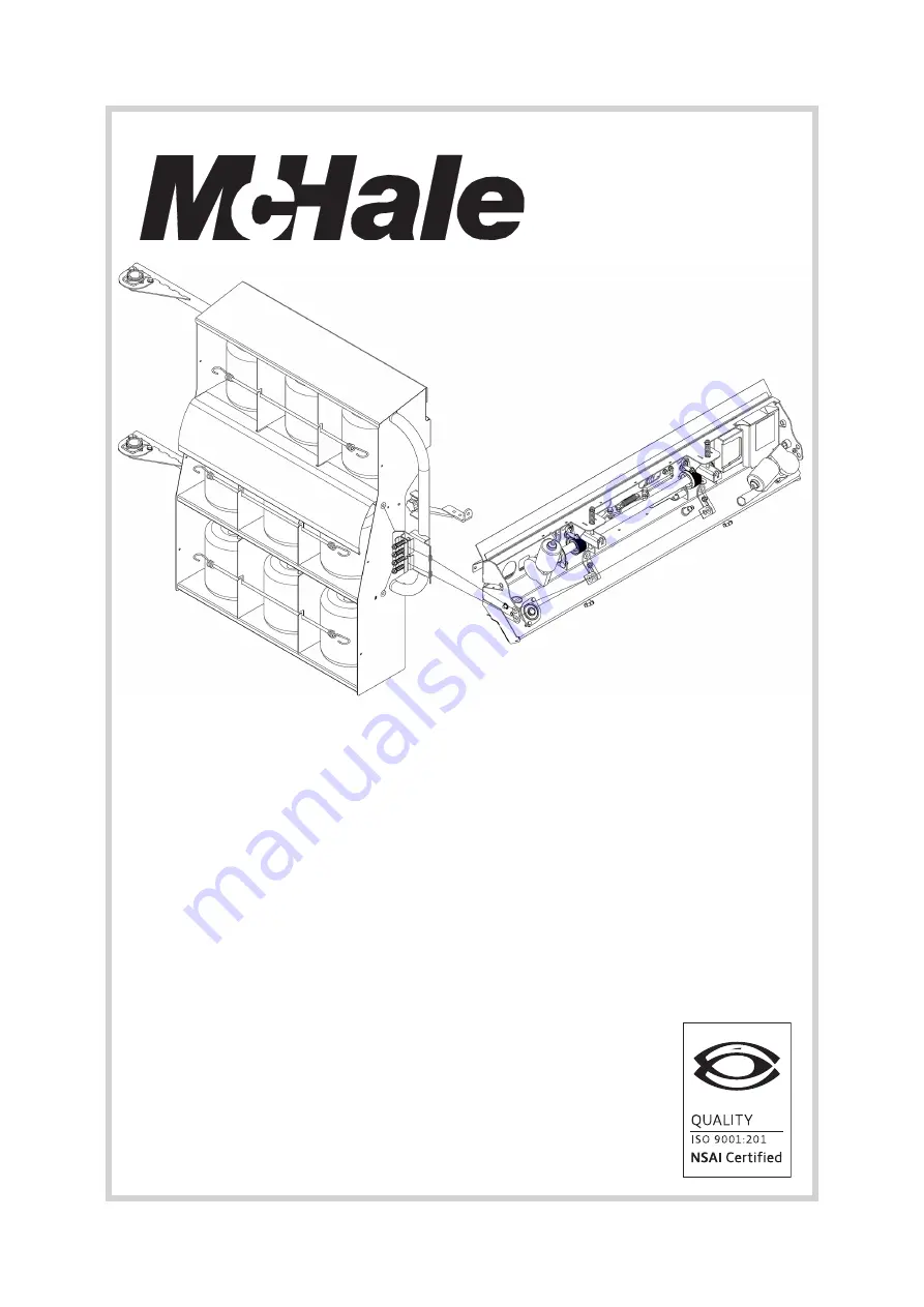
Twiner
5
5
ISO 9001:2015
Twiner
(option for the V6740/V6750 baler)
Operator Instruction Manual
Issue 4
(valid from serial number 808000)


