background image


58

HYDRAULIC SYSTEM 


Oil Supply


Check the oil level in the reservoir daily. 


Oil Condition & Replacement 

No fixed time period can be quoted for oil changes as operating conditions can vary widely 
but a visually inspection of the oil will often indicate its current overall state. Signs of a 
reduction in its condition will be apparent by changes in colour and appearance when 
compared to new oil. Oil in poor condition can be dark, smell rancid or burnt, or in some 
cases be yellow, unclear or milky in appearance indicating the presence of air or 
emulsified water. Moisture resulting from condensation can become entrapped in the oil 
causing emulsification that can block the return line filter, consequentially the filter system 
will be by-passed and the oil and any possible contaminants present will continue to 
circulate without filtration risking damage to hydraulic components. All are indications or 
conditions that will require replacement of the oil. 


Hydraulic oil is a vital component of the machine; contaminated oil is the root cause of 
70% of all hydraulic system failures. Contamination can be reduced by the following: 


  Cleaning around the reservoir cap before removal, and keeping the tank area clean. 


  Use of clean containers when replenishing the system. 


  Regular servicing of the filtration system. 


Filtration System 

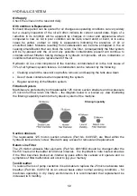
Machines are protected by both replaceable 125 micron suction strainers and low pressure 
25 micron full flow return line filters – the diagram below is a ‘scaled up’ view illustrating 
the filtering capability built into the hydraulic system of the machine:  


Suction strainers 

The replaceable 125 micron suction strainers 

(Part No. 8401097)

 are fitted within the 

hydraulic tank and are ‘screw’ fitted with easy access for removal and replacement.  


Return Line Filter 

The 25 micron absolute filter elements 

(Part No. 8401089)

 should be changed after the 

first 50 hours and thereafter at 500-hour intervals.  It is important to note hours worked as 
if the filter becomes blocked an internal by-pass within the canister will operate and no 
symptoms of filter malfunction will occur to jog your memory. 


Tank Breather 

To reduce the risk of pump cavitation it is advisable to replace the 25 micron absolute tank 
breather 

(Part No. 8401014)

 on an annual basis under normal working conditions – for 

machines operating in dry dusty environments it is recommended that replacement be 
increased to 6 monthly. 
 

Filtering Capability  

Summary of Contents for ECON HEDGEMASTER Mk3

Page 1: ...Publication 649 April 2010 Part No 22674 49 Revision 08 10 12 Operator Manual ECON HEDGEMASTER Mk3 Mid Mounted Hedgecutter Mower ...

Page 2: ...r to verify that your machine has been registered with McConnel Limited IMPORTANT During the initial bedding in period of a new machine it is the customer s responsibility to regularly inspect all nuts bolts and hose connections for tightness and re tighten if required New hydraulic connections occasionally weep small amounts of oil as the seals and joints settle in where this occurs it can be cur...

Page 3: ......

Page 4: ...ample may require particular care when packing to avoid damage in transit 1 04 This warranty does not extend to any product from which McConnel Ltd s serial number plate has been removed or altered 1 05 The warranty policy is valid for machines registered in line with the terms and conditions detailed and on the basis that the machines do not extend a period of 24 months or greater since their ori...

Page 5: ...ld be undertaken within two days of the failure Claims submitted for repairs undertaken more than 2 weeks after a failure has occurred or 2 days after the parts were supplied will be rejected unless the delay has been authorised by McConnel Ltd Please note that failure by the customer to release the machine for repair will not be accepted as a reason for delay in repair or submitting warranty clai...

Page 6: ...be deemed to be a waiver of any other term 4 02 If any provision of this limited warranty shall violate any applicable law and is held to be unenforceable then the invalidity of such provision shall not invalidate any other provisions herein 4 03 Applicable law may provide rights and benefits to the purchaser in addition to those provided herein McConnel Limited ...

Page 7: ...istances to avoid the entrapment with human body parts BS EN ISO 14120 2015 Safety of machinery Guards general requirements for the design and construction of fixed and movable guards BS EN 4413 2010 Hydraulic fluid power Safety requirements for systems and their components McCONNEL LIMITED operates an ISO 9001 2008 quality management system certificate number FM25970 This system is continually as...

Page 8: ...ade retaining bolts and fasteners are secure and tight Ensure all head bolts and nuts are tight Lubricate the driveline universal joints and telescoping members daily Grease the rotor and roller bearings and inspect their condition Inspect for any oil leaks or damaged hoses Inspect for worn or damaged decals and safety instructions Replace unreadable damaged or missing safety decals Follow the ope...

Page 9: ......

Page 10: ...e connections are tight The Hyd Valve hose connections are tight The Hyd Valve controls function properly There are no damaged hoses The Oil level is to the green mark on the tank sight glass There is no evidence of Hydraulic oil leaks Flails are not missing chipped broken or excessively worn The Flail bolts are tight The Front Rear Flaps are fittrd and in good condition The Front hood is in place...

Page 11: ...he tyres are in good condition with correct pressure The wheel nuts are tight The tractor brakes are in good condition The steering linkage is in good condition There are no visible oil leaks The hydraulic controls function properly The ROPS or ROPS cab is in good condition The seatbelt is in place and in good condition The 3 point hitch is in good condition The drawbar pick up hook is secure in g...

Page 12: ...e connections are tight The Hyd Valve hose connections are tight The Hyd Valve controls function properly There are no damaged hoses The Oil level is to the green mark on the tank sight glass There is no evidence of Hydraulic oil leaks Flails are not missing chipped broken or excessively worn The Flail bolts are tight The Front Rear Flaps are fittrd and in good condition The Front hood is in place...

Page 13: ...he tyres are in good condition with correct pressure The wheel nuts are tight The tractor brakes are in good condition The steering linkage is in good condition There are no visible oil leaks The hydraulic controls function properly The ROPS or ROPS cab is in good condition The seatbelt is in place and in good condition The 3 point hitch is in good condition The drawbar pick up hook is secure in g...

Page 14: ...ormal distribution of use where the noise fluctuates between zero and maximum The figures assume that the machine is fitted to a tractor with a quiet cab with the windows closed in a generally open environment We recommend that the windows are kept closed With the cab rear window open the equivalent daily personal noise exposure will increase to a figure within the range 82 88 dB At equivalent dai...

Page 15: ......

Page 16: ...ructions 13 PTO Driveshaft Installation 17 Controls 18 Operating Principals 20 Electric Switchbox Controls 21 Monolever Controls 25 V4 Proportional Controls 29 Preparation Precautions 42 Emergency Stopping 43 Operating Speeds 44 Safety Breakaway 45 EDS 45 Lift Float Option for Ground Work 46 Hedgecutting Procedure 47 Hazards Dangers 48 Overhead Power Lines 49 Flail Types 51 Maintenance Information...

Page 17: ......

Page 18: ...result in damage to either machine or equipment if not observed carefully NOTE An operating procedure technique etc which is considered essential to emphasis LEFT AND RIGHT HAND This term is applicable to the machine when attached to the tractor and is viewed from the rear this also applies to tractor references MACHINE DEALER INFORMATION Record the Serial Number of your machine on this page and a...

Page 19: ...kaway Unrivalled Arm Geometry Excellent Cutting Visibility High Capacity Oil Tank 227 Litre 45HP Hydraulics Choice of Control Systems Choice of Attachments Optional Extras Lift Float Kit Oil Cooler Road Lighting Kit Reach Dimensions A 6 4m 21 0 B 6 2m 20 3 C 4 26m 14 0 D 3 5m 11 5 E 5 0m 16 5 ...

Page 20: ... being detected with the machine s operation it must be stopped immediately and not used again until the fault has been corrected by a qualified technician POTENTIAL SIGNIFICANT DANGERS ASSOCIATED WITH THE USE OF THIS MACHINE Being hit by debris thrown by rotating components Being hit by machine parts ejected through damage during use Being caught on a rotating power take off PTO shaft Being caugh...

Page 21: ...ly before starting to note obstacles and remove wire bottles cans and other debris Use clear suitably sized warning signs to alert others to the nature of the machine working within that area Signs should be placed at both ends of the work site It is recommended that signs used are of a size and type specified by the Department of Transport and positioned in accordance with their and the Local Hig...

Page 22: ... fitted Never turn a machine cutting head to an angle that causes debris to be ejected towards the cab Never start or continue to work a machine if people are nearby or approaching Stop and wait until they are at a safe distance before continuing WARNING Some cutting heads may continue to freewheel for up to 40 seconds after being stopped Never attempt to use a machine on materials in excess of it...

Page 23: ...ested Warning Signs Required Road works ahead warning sign with a supplementary Hedge cutting plate For 1 mile or appropriate shorter distance may be added to the plate Road narrows warning signs with supplementary Single file traffic plate White on blue Keep right arrow sign on rear of machine Note this applies to UK Market machines where traffic passes to the right of a machine working in the sa...

Page 24: ... Minimum HP requirements All models 75HP Linkage Category 2 for mounting of the rear oil tank PTO shaft Tractor must be equipped with a live drive PTO to enable forward motion to be stopped while the flailhead continues to operate Check Chains Stabilizers Check chains or stabilizers must be fitted and tightened ...

Page 25: ...g with experienced operators this can be reduced to 10 All factors must be addressed in order to match the type and nature of the equipment added to the circumstances under which it will be used in the instance of Power Arm Hedgecutters it must be remembered that the machines centre of gravity during work will be constantly moving and will differ from that during transport mode therefore balance b...

Page 26: ...nitial filling of the oil reservoir periodic oil changes and replenishment purposes the following hydraulic oils or a good quality equivalent are recommended NOTE Only use oils that are ISO 18 13 or cleaner Manufacturer Cold or Temperate Climate Hot Climate BP Bartran 46 Energol HLP HM 46 Bartran 68 Energol HLP HM 68 CASTROL Hyspin AWH M 46 Hyspin AWH M 68 COMMA Hydraulic Oil LIC 15 Hydraulic Oil ...

Page 27: ...e controls and adjust the position of the cutting head Transportation When travelling down the road the cutting head should be carried with the flails facing towards the tractor The first arm should be vertical and the second and third rams should be carefully closed until the skid bears against the ram guard plate on the first arm and the roller drops into the vee notch in the footstep The second...

Page 28: ... the underframe using the cutting head ram Fully close 1st ram and fold arms up tight Remove hoses from tractor and plug cap ends Clean and plug cap motor hoses and stow away neatly Mounting Mounting the machine is a reversal of above Ensure the socket has seated squarely on the underframe plugs before re fitting the securing bolts Check bolts after first hours of operation for security WARNING Ke...

Page 29: ...OP THE TRACTOR ENGINE Important Note The front flap acts to stop most material being discharged from the front of the cutting head Always keep the guard adjusted as low as possible Wire with a flapping end can be dangerous not only to the operator but possibly to passers by ALL wire must be removed before re starting work Operators are advised to wear ear protectors Operators must ensure that any ...

Page 30: ...erable care has to be taken The HM3E mower would have approximately 500lbs 225 kilos of weight added either as water ballast or the Econ plug in weight assembly which ever was the better option for the particular mower tractor combination Note Even if the Econ Package Deal states that the weight assembly would be used sometimes it is better to use tractor wheel weights and or water ballast which e...

Page 31: ...sion Brackets LH RH 2 Pin R Clip 3 Mid Offside Bracket 4 Packer 5 Rear Axle Bracket 6 Rear Bracket Lower 7 Underframe 8 Clamp Plate Rear Bolt Nyloc Nut 9 Clamp Plate Mid Bolt Nut 10 Front Mounting Bolt 11 Front Bracket ...

Page 32: ... alternatively use larger bolts which clamp around the axle If the mounting holes are offset to one side of the mounting boss the bracket will need gusseting to maintain sufficient strength Remove excess material from the plate to clear lower link bracket etc and fit bracket under axle The lower part of the rear bracket item 6 is not drilled to allow it to be offset if required to clear the 3 poin...

Page 33: ...PTO installation Control Box Mounting The rectangular bracket supplied together with the telescopic floor mounted pedestal should be bolted in a suitable position to allow the control box to be mounted where it is convenient for easy operation The control box requires a 12 volt DC 10 Amp continuous supply to the two pin plug and socket supplied It should be connected positive to the red cable and ...

Page 34: ...thout the need to shorten providing it allows for a minimum 150mm 6 overlap when fitted If the shaft is longer subtract the required shaft length plus an additional 75mm 3 the resulting figure is the excess length that will need to be removed from each half of the shaft Cutting the PTO Shaft Separate the two halves and using the measurement obtained above shorten both the plastic guarding and the ...

Page 35: ... fluid level and top up if necessary 7 Ensure that the locking Allen screws for the main rotor bearing are kept secure Check twice daily If screws become insecure damage to the motor will occur Arm Movements Hydrafloat The degree of float in the arm and hence the reduction of drag of the head on the ground is governed by the arm extension or reach and hydraulic cushioning selected by the operator ...

Page 36: ...5 bar 750 800 lb in however this figure may be increased to a maximum 133 bar 2000 lb in if required Arm Lowering Speed Adjustment Fitted at the opposite side of the valve block to the accumulator are two control valves These are used to control the rate in which the 1st and 2nd arms will fall not the lifting speed Normally set at position No 1 the lower valve controls the 1st arm and the upper va...

Page 37: ...d the most comfortable view of the cutting operation therefore Watch well in front of the cutting head Steer to a near full cutting head width to achieve maximum acreage covered Set controls to achieve level cutting particularly on bank work NOT THIS BUT THIS Travel at the right speed to give a clean cut no hairy pieces stuck up but at a high enough speed to match the high performance capability o...

Page 38: ... shown below Press the switch down for Power ON LED light on Press the switch up for Power OFF LED light off Power ON Power OFF LOCATION FUNCTION OF CONTROLS 1 1st Ram Lift 1 Control 2 3rd Ram Reach Control 3 4th Ram Angle Control 4 5th Ram Breakaway Control 5 2nd Ram Lift 2 Control A Power On Off Emergency Stop B N A C Head Float Angle Lift Option D Rotor On Off Electric RCV models E Rotor Direct...

Page 39: ...22 ARM OPERATION SWITCHBOX CONTROL ...

Page 40: ...at ON HEAD FLOAT OPERATION Angle Float standard Lift Float optional ROTOR OPERATION Selection of Rotor Cutting Direction where applicable Uphill Cutting Downhill Cutting Angle Float ON Lift Float ON Angle Float OFF Lift Float OFF ...

Page 41: ...ill be lit to signify the rotor is on if the LED does not light the switch was not held in its up position for long enough and the rotor will not have started repeat the process again holding the switch upwards for a longer period Rotor Start Switching the Rotor Off Stopping the rotor is performed by switching either the Rotor Power Switch D or the Rotor Direction Switch E to the central off posit...

Page 42: ...ow Rotate the switch clockwise to Power ON LED light on Press the switch to Power OFF or Emergency Stop LED light off LOCATION FUNCTION OF CONTROLS 6 1st Ram Lift 1 Control 7 3rd Ram Reach Control 8 4th Ram Angle Control 9 5th Ram Breakaway Control 10 2nd Ram Lift 2 Control F Power On Off Emergency Stop G N A H Head Float Angle Lift Option I Rotor On Off Electric RCV models J Rotor Direction if ap...

Page 43: ...26 ARM OPERATION MONOLEVER CONTROL ...

Page 44: ...at ON HEAD FLOAT OPERATION Angle Float standard Lift Float optional ROTOR OPERATION Selection of Rotor Cutting Direction where applicable Uphill Cutting Downhill Cutting Angle Float ON Lift Float ON Angle Float OFF Lift Float OFF ...

Page 45: ...ill be lit to signify the rotor is on if the LED does not light the switch was not held in its up position for long enough and the rotor will not have started repeat the process again holding the switch upwards for a longer period Rotor Start Switching the Rotor Off Stopping the rotor is performed by switching either the Rotor Power Switch D or the Rotor Direction Switch E to the central off posit...

Page 46: ...FLAIL START 9 ROTOR STOP This button stops the rotor when the button is pressed the control unit will emit a single beep and the screen will momentarily display FLAIL STOP 9 the LED lights above both rotor start buttons will be illuminated for approximately 10 seconds during this period the rotor start buttons will be disabled to allow sufficient time for the rotor to power down When the LED light...

Page 47: ...ntrol unit will emit a single beep the LED light will illuminate and the screen will momentarily display ANGLE FLOAT 9 To deselect press and hold in the lower frontal button B1 on the joystick control and roll the left hand thumbwheel T1 backwards the control unit will emit a single beep the LED light will go out and the screen will momentarily display ANGLE FLOAT X NOTE When selecting or deselect...

Page 48: ...k control and roll the right hand thumbwheel T2 backwards the control unit will emit a single beep the LED light will go out and the screen will momentarily display LIFT FLOAT X NOTE When selecting or deselecting the function the thumbwheel T2 should be allowed to return to its centre position before releasing the lower frontal button B1 All models with v4 08 software onwards With the function eng...

Page 49: ...of control available for selection and de selection of the functions activation via the control unit refer to 1 below or activation via the joystick controls refer to 2 below 1 Pressing the button momentarily will select Diverter Valve 1 when activated the control unit will emit a single beep the LED light will illuminate and the screen will momentarily display DIVERTER VALVE 1 9 Pressing the butt...

Page 50: ... is displayed on the control box screen as SLEW TELE SWAP 1 Press the swap button once to select swap mode when activated the control unit will emit a single beep the LED light will illuminate and the screen will momentarily display SLEW TELE SWAP 9 Pressing the button again will deselect the function the control unit will emit a single beep the LED light will go out and the screen will momentaril...

Page 51: ...ll activate Auto Reset the control unit will emit a single beep the LED light will illuminate and the screen will momentarily display AUTO RESET 9 Pressing the button again will deselect the function the control unit will emit a single beep the LED light will go out and the screen will momentarily display AUTO RESET X ...

Page 52: ... the opposing functions this procedure is performed by accessing the settings menu on the control unit via the screen and menu buttons LH RH Swap Shortcut Press and hold 9 X on Control Unit for 3 seconds unit will bleep to confirm FLOAT SELECTION DE SELECTION Operate thumbwheels to their furthest points or to select or deselect float functions ANGLE BREAKAWAY OPERATION DIVERTER VALVE SELECTION Rot...

Page 53: ...36 ARMHEAD OPERATION JOYSTICK CONTROLS ...

Page 54: ...37 ARMHEAD OPERATION JOYSTICK CONTROLS ...

Page 55: ...cess Menu Buttons Power on off switch E Stop Speaker audible confirmation Command Button 9 Command Button X Navigate Forward Button Navigate Back Button Control unit emits an audible confirmation beep when the buttons are pressed ...

Page 56: ...rward button once will display the rotor running times screen TOT displays the overall total running time of the rotor which is a cumulative total and cannot be reset JOB is a trip total for the current rotor running time and can be reset to zero by pressing and holding the X button for 3 seconds 3 Pressing either of the Rotor On buttons will activate the egg timer icon and display the rotor on im...

Page 57: ...buttons When the required screen is reached the tick 9 button should be pressed to enter the settings menu for that feature THUMB Thumbwheel Switching this allows the operator to swap over the left and right thumbwheel functions so that they control the opposing features In most cases this setting will be dictated by the operators personal preference and once chosen the operator will keep it in th...

Page 58: ... has developed a fault and should be repaired or replaced B1 and B2 Display These report the status of the 2 joystick buttons and will display ON when the button is activated or OFF when deactivated The readings below B1 and B2 on the screen record usage of the buttons EDS STATUS SCREEN Although this screen is present on all v4 controls with the exception of the voltage reading the information it ...

Page 59: ...to average cutting with occasional heavy duty work during this period check the tightness of nuts and bolts after one hour four hours and again at the end of the day retightening as and when required General Work Precautions Inspect the work area prior to operation remove any hazardous materials and note any immovable objects it may also be a wise precaution to indicate these hazards with a visibl...

Page 60: ...ing the Off Emergency Stop switch on the machine s control unit WARNING Auto Reset Machines When the Auto Reset feature is active the machines arm set is capable of unintentional movement even when the PTO is switched off and stationary Always ensure that electrical power to the machine is switched off using the Off Emergency Stop switch on the machine s control unit in emergency situations and or...

Page 61: ...king position just clear of the material to be cut Increase engine speed to a high idle and start the rotor after initial surging the rotor will run at an even speed Carefully lower the flail head into the work area and begin work Tractor Forward Speed The material being cut will determine the tractor forward speed Forward speed can be as fast as that which allows the flail head sufficient time to...

Page 62: ...tance extra care must be taken during operation to avoid this occurrence Re setting the head into the work position is carried out manually by operation of the breakaway ram Ram 5 using the control unit EASY DRIVE SYSTEM EDS The Easy Drive System EDS is an optional extra on proportional machines with v3 or v4 digital controls where fitted it provides hands free cruise control operation with automa...

Page 63: ...on the current level of retained pressure Lower the flail head into the work position release the lift control and proceed to work NOTE with the exception of EDS models occasional operation of the lift function will be required when working on downhill or uphill slopes and when reaching in or out in order to replenish the oil level within the accumulator s to retain optimum float capability Lift f...

Page 64: ...ld side first This leaves the maximum thickness of hedge on the road side to prevent the possibility of any debris being thrown through the hedge into the path of oncoming vehicles Cut the side and bottom of the road side Top cut the hedge to the height required ...

Page 65: ...E OF A HEDGE it is impossible to see any potential hazards or dangers and the position of the flail head would allow debris to be propelled through the hedge towards the tractor and operator DANGER NEVER OPERATE THE MACHINE WITH THE FLAIL HEAD ROLLER REMOVED DANGER WHEN GRASS MOWING THE ROTOR MUST ALWAYS CUT IN THE UPHILL DIRECTION WITH FRONT HOOD FITTED AND THE ROLLER POSITIONED BELOW THE CUTTING...

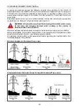
Page 66: ...ity can flashover when machinery gets close to it WARNING All operators must read the following information and be aware of the risks and dangers involved when working in the vicinity of Overhead Power Lines OHPLs Wherever possible the safest option is always to avoid working in areas close to OHPLs Where unavoidable all operators must perform a risk assessment and implement a safe procedure and s...

Page 67: ...doubt exists do not work in the area never risk the safety of yourself or others Emergency Action for Accidents Involving Electricity Never touch an overhead line even if it has been brought down by machinery or has fallen Never assume lines are dead When a machine is in contact with an overhead line electrocution is possible if anyone touches both the machine and the ground Stay in the machine an...

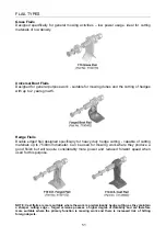
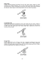
Page 68: ...eavy duty hedge cutting capable of cutting materials up to 75 80mm diameter Can be used for mowing work where they produce a good finish but will require considerably more power and reduced forward speed when used for this purpose NOTE Cast flails are more suitable where the work is predominantly hedge cutting as they maintain a sharper cutting edge forged versions possess a higher degree of durab...

Page 69: ... flail designed specifically for heavy duty hedge and grass cutting capable of dealing with materials up to 75 80mm diameter When used for mowing work they produce a better finish and performance than double edged flails requiring less power and increased forward speed Omega Flails Double edged flail for use on Omega rotors only designed specifically for heavy duty hedge cutting where they are cap...

Page 70: ...ery week BP Energrease EP2G 5 Ram pivots not fitted with grease nipples A few drops of oil daily Tractor gearbox oil 20 A Hydraulic tank Capacity 227 Litres 50 Gallons Top up daily to sight gauge on tank Do not mix grades use clean oil only and fill through cap filter Change oil completely every 1000 hours BP Energol HLP46 or exact equivalent B Gearbox Capacity 0 7L Check daily for leaks Change oi...

Page 71: ...t using a wood or leather mallet Check the bearings for excessive wear on the ball race seat on the spherical ball seat and also check if the seals are intact When assembling the rotor reverse the previous operations to the point of refitting the motor At this stage the bottom nearest ground bearing bolts should be in place but not tightened and the top bearing in line with the holes in the end pl...

Page 72: ...or e g length of wood or metal wire wrapped round bearing etc remove c Trapped or kinked hoses inspect and straighten or replace as necessary d Empty oil tank e Faulty pump see check out one f Faulty motor see check out three g Faulty relief valve see check out one h Faulty solenoid valve or power connection a Faulty relief valve see check out one b Faulty pump see check out one c Faulty motor see...

Page 73: ...pressure gauge to relief valve Disconnect hose connecting valve to motor at valve connection Operate valve manually and check pressure setting should be 2600 lb in 179 Bar Faulty filter or blocked return on motor circuit Connect low pressure gauge Start engine run PTO up to speed and should the gauge reading exceed 30 lb in 2 0 Bar then the filter elements should be changed If this does not reduce...

Page 74: ...lic system is invariably caused by the blowing off of the relief valve The blowing off may well be caused by either wrappage around the rotor bearings the partial collapse of a hydraulic hose the partial trapping of a hose dirt in the relief valve itself so that it does not close or badly worn hydraulic components caused by dirt in the system If you require any further assistance or information on...

Page 75: ...y the following Cleaning around the reservoir cap before removal and keeping the tank area clean Use of clean containers when replenishing the system Regular servicing of the filtration system Filtration System Machines are protected by both replaceable 125 micron suction strainers and low pressure 25 micron full flow return line filters the diagram below is a scaled up view illustrating the filte...

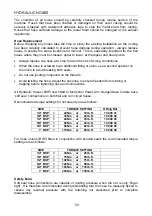
Page 76: ...the threads Avoid twisting the hose Adjust the hose line to ensure freedom from rubbing or trapping before tightening hose end connections All Hydraulic Hoses BSP now fitted to McConnel Power Arm Hedge Grass Cutters have soft seal connections on both flail and ram circuit hoses Recommended torque settings for nut security are as follows For hose unions BSP fitted in conjunction with bonded seals t...

Page 77: ... back along the body of the driveshaft the procedure and lubrication frequency is illustrated below Slide the shaft shield back into place after lubrication ensuring the clasps relocate correctly in the fixing ring always fit torque chains to the shields to stop them from rotating with the shaft during operation Shaft shield fixing clasps Insert screwdrivers into the clasps Prise clasps open to re...

Page 78: ...McConnel Limited Temeside Works Ludlow Shropshire SY8 1JL England Telephone 01584 873131 Facsimile 01584 876463 www mcconnel com ...

Reviews: