background image

34  


MBW973-SF6_MANUAL_E_V3.1


Summary of Contents for 973-SF6

Page 1: ...SF6 Analyzer 973 Operation Manual Version 973 SF6 V3 1 MBW Calibration Ltd Seminarstrasse 57 CH 5430 Wettingen Switzerland 41 56 437 28 30 Phone 41 56 437 28 40 Fax sales mbw ch www mbw ch...

Page 2: ......

Page 3: ...Evacuate the Internal Cylinder 14 SF6 Gas Connection to the Compartment 15 MEASUREMENT OPTIONS 17 Navigating the Menus 17 MEASUREMENT 19 Measurement without SO2 Option 19 Termination of Measurement 2...

Page 4: ...Selection of Languages 35 Selection of the indicated Parameters 36 Selection of Units 37 Changing Color 38 Storage of the Actual Settings 39 Restore Color Settings and Baud Rate 40 MAINTENANCE 41 Touc...

Page 5: ...other way than that described in this user s manual or outside the limits described the built in safety pro tection of the instrument may be compromised Vol SF6 All descriptions in bold italic are rel...

Page 6: ...2 MBW973 SF6_MANUAL_E_V3 1...

Page 7: ...rated touch screen The 973 may be configured for measurement of Humidity and Volume SF6 with either automatic or manually initiated Pump Back Using the bi directional RS 232 communications port all me...

Page 8: ...4 MBW973 SF6_MANUAL_E_V3 1...

Page 9: ..._MANUAL_E_V3 1 5 Operation Front Panel without SO2 Option Front Panel with SO2 Option Status of Measurement Measuring Head Keypad Menu Keys Internal Cylinder Capacity Fixed Function Keys Touch Screen...

Page 10: ...is line displays the purity in Volume SF6 Data Line 4 This line indicates the current pressure of the gas compartment The unit is kilo Pascal absolute pres sure The data lines indicating the measured...

Page 11: ...options The text on the bottom key changes to indicate the cur rently selected menu option The text of the upper keys change based on the functions available in the menu Keypad The keypad is used for...

Page 12: ...NUAL_E_V3 1 Back Panel without SO2 Option Back Panel with SO2 Option Fan Gas Inlet Quick Coupling RS 232 Serial Interface Power Socket with Main Switch Optional SO2 Sensor with Calibration Date and Re...

Page 13: ...replaced by the user The sensor has to be replaced every two years The cali bration and replacement dates are indicated on the SO2 module Gas Inlet Quick Coupling The sampling line is connected to the...

Page 14: ...10 MBW973 SF6_MANUAL_E_V3 1...

Page 15: ...ided power cable to connect the instrument to the AC power Start the instrument by turning on the power switch The dis play of the 973 comes up immediately following the proces sor s boot phase The bo...

Page 16: ...e of the sampling tube must be connected to the SAMPLE GAS inlet Note To prevent contamination the blue cover caps of the instru ment and sampling tube should always be installed when the instrument i...

Page 17: ...ube is properly connected to the 973 Press the lower right key in order to select the Control Set up menu Control Setup appears on the key while on the upper keys the available menu options are indica...

Page 18: ...k coupling from the SAMPLE GAS inlet or connect the instrument to an SF6 reclaimer Press the Ok button to start the internal cylinder evacua tion The dialogue box indicates the current internal cylind...

Page 19: ...cuated before the first measurement it is now ready to connect to the gas com partment When moving the connection from compartment to compartment there is no need to re evacuate Remove the dust caps f...

Page 20: ...16 MBW973 SF6_MANUAL_E_V3 1...

Page 21: ...t has an SO2 module installed then the user can also choose to activate or deactivate the SO2 measurement With the standard 973 SF6 configuration humidity measurement volume SF6 measurement and automa...

Page 22: ...held in the internal cylinder and not automatically pumped back For the purpose of this example select only SO2 Meas urement and Vol SF6 Measurement and disable Hu midity Measurement and Pump Back Af...

Page 23: ...ement Volume SF6 Measurement and Pump Back After Measurement is ac tivated Press the Start button The Start button and the Pump but ton turn green Because the SO2 measurement is disabled an X appears...

Page 24: ...measurement is started by pressing the Start button The vessel pressure measurement always indicates the current pressure at the 973 sample gas input After completion of the measure ment the gas compa...

Page 25: ...ted Press the Start button The Start button and the Pump but ton turn green The pump starts and the SO2 clock located next to the Start button begins to spin During the measurement SF6 gas flows from...

Page 26: ...measure ment is started by pressing the Start button The vessel pressure measurement always indicates the current pres sure at the 973 sample gas input After completion of the measurement the gas com...

Page 27: ...ual volume SF6 value is below the measuring limit of the instrument If the instrument indicates a reading of 100 for Volume SF6 service or calibration may be needed Please contact the manufacturer or...

Page 28: ...he measured air nitrogen is not stored in the internal cylinder and will be pumped to atmosphere through a small vent point in ternal to the 973 Activate the Air N2 measurement mode by selecting Hu mi...

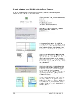
Page 29: ...nstallation you may plug the adapter into the USB port of your computer Locate the Keyspan Assistant in the default folder C Program Keyspan USB Serial Adapter Double click on K19hasst exe or launch t...

Page 30: ...er 3 and so on Click on the cell below the field Read Data from COM An arrow appears on the right side By click ing on the arrow the window for the input selec tions of the COM Port Number opens If yo...

Page 31: ...elected a check mark will appear in front of SO2 By clicking the Read button the measured values for Dew Frost Point Moisture Content SF6 Vol and Pressure are transferred into the correspond ing cells...

Page 32: ...28 MBW973 SF6_MANUAL_E_V3 1...

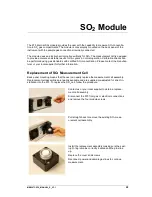
Page 33: ...or your local supplier for further information Replacement of SO2 Measurement Cell Back panel mounting means that the user can easily replace the measurement cell assembly Replacement cell assemblies...

Page 34: ...s the lower right menu key repeatedly to select the Other Settings menu Then press the Activation Codes key A window will appear where you can enter the activation code provided by the manufacturer or...

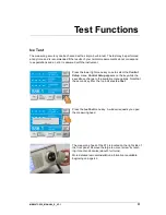
Page 35: ...t menu key once to select the Control Setup menu Control Setup appears on the key while the keys above change to the available menu options Note that the second key from the top indicates Ice Test Pre...

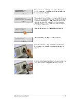
Page 36: ...from the ambient air starts to condense on the mirror This forms a frost layer on the mirror which can be strengthened if nec essary by blowing on it After reaching the low temperature and forming ic...

Page 37: ...FAIL In this case the ice test should be repeated If it continues to fail the instrument should be sent to the manufacturer or an authorized agent for evaluation and or repair Press the Ok button on...

Page 38: ...34 MBW973 SF6_MANUAL_E_V3 1...

Page 39: ...n After restart of the 973 the display language is set back to the standard configuration If you wish to save your chosen language in the power up default of the instrument then please follow the inst...

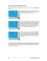
Page 40: ...available parameter the first one is again displayed and the cycle starts over Change the parameters on any of the other three data lines with the same method If you like you may clear the menu keys w...

Page 41: ...t Change other units such as Pressure Flow Rate etc with the same method In addition to setting the Pressure units the mode may be set to either absolute or relative mode Note Relative mode is often r...

Page 42: ...you wish to change Note that the fore color of the data line changes with each press of the key Change the fore color on any of the other data lines with the same method Back Color Back color affects...

Page 43: ...onds You hear a beep and a window appears asking for confir mation to store the current configuration as the new de fault By pressing the Ok button the current instrument settings will be stored as th...

Page 44: ...on of the data lines Colors The default configuration includes the front and back ground colors selection Restore Color Settings and Baud Rate Press and hold the number 9 on the keypad for about 5 sec...

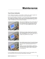
Page 45: ...ectly you will hear two short beeps and a key in the upper right corner will turn yellow If not release the Enter key and try again With the tip of your finger press the center of the yellow key in th...

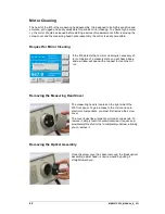
Page 46: ...s necessary af ter completion of a measurement you will hear a beep and a window will open with a request to clean the mir ror Removing the Measuring Head Cover The measuring head is located on the ri...

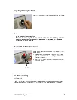
Page 47: ...he mirror surface Reassemble the Mirror Components Reassemble the mirror components in the reverse order of disassembly 1 Install the optical assembly taking note of the guide pin Ensure that the arro...

Page 48: ...44 MBW973 SF6_MANUAL_E_V3 1...

Page 49: ...20 6 m stainless steel armored PTFE tubing Optimum Response Injection System Custom fit foam lined Peli 1620 2 5 m English German French Italian Spanish or Russian Pressure calibration 2 point dew fro...

Reviews: