22
Circulator Blower Speed Adjustment
WARNING
To avoid personal injury or death due to electrical shock,
turn OFF power to the furnace before changing speed taps.
Furnaces are equipped with a EEM circulator blower motor.
This provides ease in adjusting blower speeds. Refer to the
Blower Performance Data in the back of the manual for prop
-
er selection of heating and cooling speeds.
To adjust the circulator blower speed, proceed as follows:
1. Motor speed Tap wiring must remain in factory position
on the control board and motor
2. There are 4 speed Tap wires to the motor T1, T2, T3, T4.
)
3. There are 5 speeds available, depending on DIP
switch settings mentioned in air flow tables for each
size furnace.
4. Cooling speed can be adjusted by adjusting S1-1, S1-
2, S1-3 (see cooling airflow Chart for reference).
5. Heating speed can be adjusted by adjusting S2-1,
S2-2 (see Heating airflow Chart).
6. Circulation / Continuous Fan speed can be adjusted by
adjusting S2-3, S2-4 (see Circulation airflow Chart).
7. Verify Proper temperature rise as outlined in the
Temperature Rise section of Startup Procedure and
Adjustment. Please refer to the tables below for dip
switch settings.
CONNECTOR ID
DESCRIPTION
CONNECTOR VOLTAGE
L
LINE, L1
LINE, L1
G
GROUND
CHASSIS GROUND
N
LINE, L2
LINE, L2
C
SIGNAL COMMON 24VAC COMMON
1
TAP 1
24VAC
2
TAP 2
24VAC
3
TAP 3
24VAC
4
TAP 4
24VAC
5
TAP 5
24VAC
Motor Tap Identification
S1-4
Min
Nom
Max
Units
ON
*
150
Seconds
OFF
100
Seconds
Heat Off Delay (S1-4)
*
= DEFAULT SETTING
This measured input must not be greater than the input indi-
cated on the unit rating plate.
5.
Turn ON gas and relight appliances turned off in step
1. Ensure all the appliances are functioning properly
and that all pilot burners are operating.
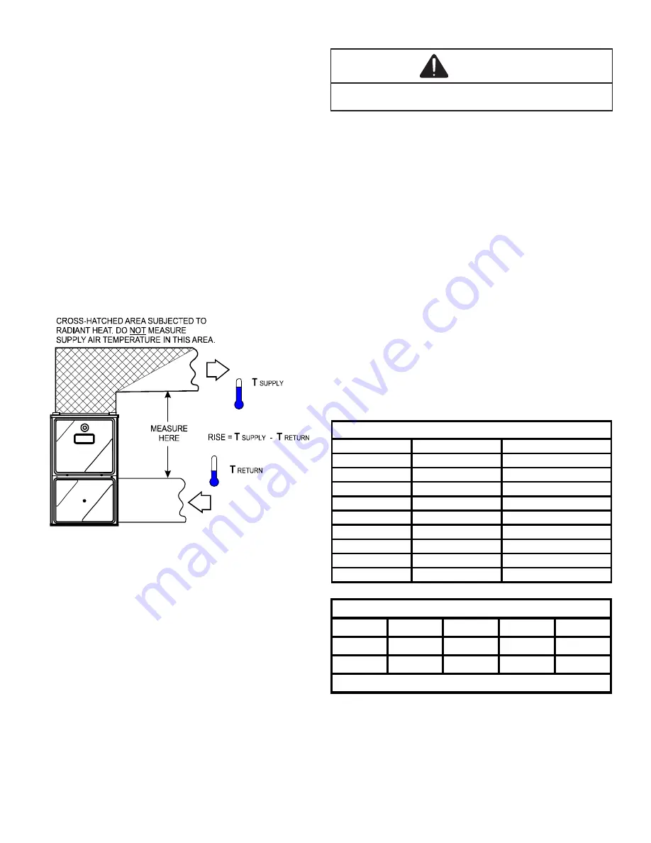
Temperature Rise
Air temperature rise is the temperature difference between
supply and return air. The proper amount of temperature rise
is usually obtained when the unit is operated at the rated in-
put with the “as shipped” blower speed. If the correct amount
of temperature rise is not obtained, it may be necessary to
change the blower speed.
An incorrect temperature rise can cause condensing in or
overheating of the heat exchanger. Determine and adjust the
temperature rise as follows. The temperature rise must be
within the range specified on the rating plate or Specification
Sheet applicable to your model.
(Please contact your dis
-
tributor or our website for the applicable Specification Sheet
referred to in this manual.)
SUPPLY
AIR
RETURN
AIR
Temperature Rise Measurement
1.
Operate furnace with burners firing approximately
15 minutes. Ensure all registers are open and all
duct dampers are in their final (fully or partially open)
position.
2. Place thermometers in the return and supply ducts as
close to the furnace as possible. Thermometers must
not be influenced by radiant heat by being able to
“see” the heat exchanger.
3. Subtract the return air temperature from the supply
air temperature to determine the air temperature rise.
Allow adequate time for thermometer readings to
stabilize.
4. Adjust temperature rise by adjusting the circulator
blower speed. Increase blower speed to reduce
temperature rise. Decrease blower speed to increase
temperature rise. Refer to the following section for
speed changing details.


