Installation and Operational Instructions for
ROBATIC
®
-clutch Type 500.1_ _ and Type 580.1_ _
Sizes 3 – 9
(B.5.0.GB)
28/08/2007 TK/RB/RJ
Chr. Mayr GmbH + Co. KG
Tel.: 08341 / 804-241
Eichenstraße 1
Fax: 08341 / 804-422
87665 Mauerstetten
http://www.mayr.de
Page 5 of 8
Germany
eMail:
State of Delivery
Please check the state of delivery immediately according to the
Parts List!
mayr
®
will take no responsibility for belated complaints.
Please report transport damage immediately to the deliverer.
Please report incomplete delivery and obvious defects to the manu-
facturer.
Function
ROBATIC
®
-clutch devices are energised to engage, electromag-
netic pole face clutches.
By applying DC voltage to the magnetic coil in the coil carrier (1/2),
a magnetic field is built up. This pulls the armature disk (4) against
the rotor (3).
The torque is transmitted via frictional locking.
Please Observe:
In new condition, torque transmission first takes
place via the metal outer pole on the rotor (3)
and, after a short operation period, then additionally via the inner
pole. After the entire run-in procedure, an even frictional
combination occurs on the metal poles and on the friction linings
lying between them.
Design
ROBATIC
®
-clutches have Electrical Protection IP 54 and Insulation
Class F (up to 155 °C) for coil, casting compound a nd connection
strands. On the design with a connection terminal, the connection
terminal itself corresponds to Protection Class IP00.
At 100 % duty cycle, the coil has a temperature of c. 65 °C.
The surfaces on the coil carrier (1/2), rotor (3) and
flange hub (7) are phosphated, the armature disk (4) is gas nitro-
carburized (friction surfaces are ground), and the transmission
spring is made of stainless steel.
The clutch rotor (3) is pilot bored or finished bored with a keyway
acc. DIN 6885. When the rotor bore and keyway are produced
customer-side, the Guidelines on page 6 of the Installation and
Operational Instructions, “Boring the Rotor Hub” must be followed!
Explanation of Terms
The nominal torque M
2
is the largest transmittable torque (after
run-in has been completed), with which the closed clutch can be
loaded without slipping occurring.
The relative duty cycle is the ratio of duty cycle to backlash
duration in percent (% duty cycle).
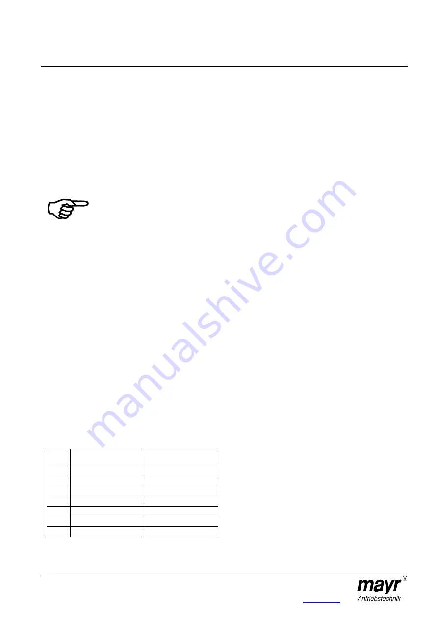
Table 2
Size
Friction work Q
a
[J]
Clutch speed n
min
[rpm]
3
16
300
4
29
250
5
55
200
6
105
160
7
200
130
8
380
120
9
600
100
Torque Characteristics
In new condition, c. 50 % of the catalogue nominal torque (M
2
)
is transmitted.
The components reach the catalogue nominal torque when the
friction surfaces are run in. Please take c. 100 – 200 switchings in
dynamic operation, a typical speed of c. 500 to 1000 rpm and a
medium friction work (see Table 2) as rough reference values.
Longer slipping on the clutch, especially at low speeds, is to be
avoided, as this can lead to scoring and therefore to damage to the
friction surfaces.
Clutches used in static or virtually static operation do not reach the
nominal torque (M
2
) shown in the Technical Data (Table 1).
On request, the clutch can also be run in manufacturer-side. In this
case, please ensure that the customer-side installation is carried
out exactly according to the specifications, in order to re-create the
best possible friction conditions. Also, the “friction carbon” must not
be wiped away.
If the clutches are run in manufacturer-side to the nominal torque
and then run in static or virtually static operation, please expect a
nominal torque reduction of c. 60 to 70 %. This is the case if the
clutch under-runs the speed or friction work (Q
a
) given in Table 2.
For static and virtually static applications, we therefore recommend
our "doubled magnetic flow designs", Type series 500.3_ _.0
(available on request).
Run-in conditions
Please carry out an "artificial" run-in if a run-in procedure on the
machine is not possible for the application (see section Torque
Characteristics). This is the case e.g. when the friction work, the
speed or the switching frequencies are too low.
Run-in Possibility 1
Apply a voltage c. 1/3 of U
Nom
(do not apply nominal voltage!).
Speed
on sizes 3 – 6: c. 50 rpm,
on sizes 7 – 9: c. 30 rpm
c. 2 – 3 minutes slipping against blocked output.
Run-in Possibility 2
Synchronize against unblocked output by producing a larger
rotating mass and / or by synchronizing at higher speed
(values should lie above the minimum values, Table 2)
Allow to synchronize for c. 2 – 3 minutes.


