


Installation and Operational Instructions for
ROBA
®
-ES Couplings Type 94_._ _ _._ Sizes 14
– 65
(B.9.6.EN)
11/03/2022 TK/GH/GC/MD
Chr. Mayr GmbH + Co. KG
Eichenstraße 1, D-87665 Mauerstetten, Germany
Phone: +49 8341 804-0, Fax: +49 8341 804-421
Page 19 of 29
Joining Both Coupling Hubs
Due to the pre-tension on the flexible elastomeric element (6), an
axial installation force is required when joining the coupling hubs
(Figs. 2 und 3 / page 4).
The force required can be reduced by lightly greasing the
elastomeric element.
Use PU-compatible lubricants (e. g. Vaseline or
a multi-purpose grease based on mineral oil,
NLGI Class 2, with a basic oil viscosity of
approx. 200 mm
2
/s).
After joining both coupling hubs, no axial
pressure must be placed on
the
elastomeric
element (6).
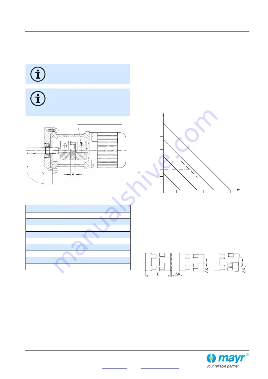
Keep to distance dimension “E” acc. Fig. 15
and Table 14!
Please see guideline under ATEX!
Fig. 15
ROBA
®
-ES with clamping hubs
Table 14: Distance Dimension "E"
Size
Distance dimension “E” (Fig. 15)
14
13 mm
19
16 mm
24
18 mm
28
20 mm
38
24 mm
42
26 mm
48
28 mm
55
30 mm
65
35 mm
Coupling Alignment
Exact alignment of the coupling increases the coupling service
lifetime and reduces the load on the shaft bearings. In most of the
applications, coupling alignment using a straight edge in two
levels vertical to each other is sufficient.
However, we recommend alignment of the coupling (of the shaft
ends) using a dial gauge or laser on drives operating at very high
speeds.
Permitted Shaft Misalignments
ROBA
®
-ES couplings compensate for radial, axial and angular
shaft misalignments (Fig. 17) without losing their backlash-free
function. However, the permitted shaft misalignments indicated in
Table 10 on page 12 must not simultaneously reach their
maximum value. If more than one kind of misalignment takes
place simultaneously, they influence each other. This means that
the permitted misalignment values are dependent on one another,
see Fig. 16.
The sum total of the actual misalignments in percent of the
maximum value must not exceed 100 % (see example and Fig.
16).
The permitted misalignment values given in Table 10 refer to
coupling operation at nominal torque, an ambient temperature of
+30 °C and an operating speed of 1500 rpm. If the coupling is
operated in other or more extreme operating conditions, please
contact the manufacturers.
Fig. 16
Example:
ROBA
®
-ES, Size 24, Type 940.000.A
Axial displacement occurrence ΔK
a
= 0.56 mm equals 40 % of
the permitted maximum value ΔK
a
= 1.4 mm.
Angular misalignment occurrence ΔK
w
= 0.27° equals 30 %
of
the permitted maximum value ΔK
w
= 0.9°.
=> permitted radial misalignment ΔK
r
= 30 % of the maximum
value
ΔK
r
= 1.0
mm => ΔK
r
= 0.3 mm
Axial
Radial
Angular
displacement
misalignment
misalignment
Fig. 17
20
30
%
25
%
75
%
0%
50
%
20
40%
40
30%
60
60
80
80
100
100
Right hub shown
mirrored
Δ K
w
[%]
Angular misalignment
Δ K
a
[%] Axial displacement
Δ K
r
[%
]
Ra
d
ia
l m
is
a
lig
n
m
e
n
t