


Installation and Operational Instructions for
ROBA
®
-ES Couplings Type 94_._ _ _._ Sizes 14
– 65
(B.9.6.EN)
11/03/2022 TK/GH/GC/MD
Chr. Mayr GmbH + Co. KG
Eichenstraße 1, D-87665 Mauerstetten, Germany
Phone: +49 8341 804-0, Fax: +49 8341 804-421
Page 15 of 29
Elastomeric Elements (6)
The elastomeric elements (6) are the central element of the
ROBA
®
-ES-coupling. They define the application field as well as
the shaft connection behavior via the permitted torque, the
rigidity, the damping and the misalignment values.
By using a unique polyurethane material and a special injection
procedure, it is possible to achieve a high dimensional accuracy
and evenness in the teeth of the elastomeric element (6).
The elastomeric elements are available in different shore
hardnesses (see Table 9).
The teeth of the elastomeric element (6) are chamfered at the
sides. This makes blind assembly easier.
Agent Resistance
– Elastomeric Elements (6)
The elastomeric elements (6) are very resistant against
pure mineral oils (lubricating oils)
anhydrous greases.
They have a similar resistance against fuels such as
regular-grade petroleum
diesel oil
kerosene.
Damage may occur after longer exposure to
alcohols
aromatic fuels (super/four star petrol).
The elastomeric element material used is resistant to hydrolysis.
In contrast to other polyurethane materials, water (including sea
water) causes, even after years of exposure, no particular
changes to the mechanical characteristics.
Hot water, however, reduces the mechanical strength.
Temperature Resistance
– Elastomeric Elements
(6)
The ambient temperatures present during operation have a
considerable effect on the torque, the rigidity or the damping
behavior of the coupling. The permitted temperature ranges
according to Table 13 must be maintained.
The temperature influence must be taken into account during
coupling dimensioning (pages 25 and 26).
General Installation Guidelines
The maximum bore diameter according to the Technical Data
may not be exceeded.
The hub bores are usually produced with tolerance H7, and
with tolerance F7 for clamping hubs. The required shaft
tolerance depends on the hub type used. We recommend the
following shaft tolerances:
For clamping hubs, shrink disk hubs and key hubs: k6
For split clamping hubs: g6
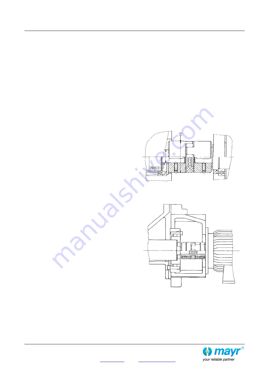
The recommended bore tolerances are to be produced using
the position and tolerance width as references; at the same
time, please keep to the shaft run-out tolerance of 0.05 mm to
"A" (see Fig. 5).
After producing the finish bore, please clean it using suitable
cleaning agents.
The shaft surfaces should be finely turned or ground
(Ra = 0.
8 μm).
The required yield point for the shafts used is at least 350
N/mm² (St60, St70, C45, C60).
Fig. 5
ROBA
®
-ES
with keyways
Fig. 6
ROBA
®
-ES
with shrink disk hubs