


Installation and Operational Instructions for
ROBA
®
-ES Couplings Type 94_._ _ _._ Sizes 14
– 65
(B.9.6.EN)
11/03/2022 TK/GH/GC/MD
Chr. Mayr GmbH + Co. KG
Eichenstraße 1, D-87665 Mauerstetten, Germany
Phone: +49 8341 804-0, Fax: +49 8341 804-421
Page 18 of 29
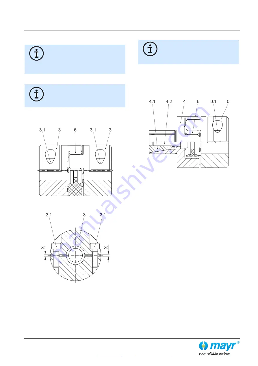
Installation of the Split Clamping Hubs
(Item 3 / Figs 12 and 13)
The hub bores and the shaft ends must be
completely grease-free during installation.
Greasy or oily bores or shafts do not
transmit the maximum coupling torque.
Please make sure that the key sits securely
for designs with keyway.
1) Mount the coupling hubs (3) onto both shaft ends using a
suitable device and bring them into the correct position.
The coupling design with two split clamping
hubs (Type 94_._33._) allows a replacement of
the elastomeric element / coupling without
dismantling the input or output side due to the
possibility of radial installation.
2) Tighten the clamping screws (3.1) alternately and in several
tightening sequences to the tightening torque stated in Table
6. Please make sure that the gap "X" (Fig. 13) has the same
size on both hub sides. If necessary, re-adjust it.
Fig. 12
Fig. 13
Installation of the Expansion Hub (Item 4 / Fig. 14)
The clamping surfaces and the bores of the
hollow shafts must be completely grease-
free during installation.
Greasy or oily bores or shafts do not
transmit the maximum coupling torque.
1) Loosen the tensioning screw (4.2) and the tensioning cone
(4.1).
2) Insert the expansion hub (4) with the tensioning screw (4.2)
and the tensioning cone (4.1) into the hollow shaft and bring it
into the correct position.
3) Tighten the tensioning screw (4.2) using a torque wrench
evenly to the required torque acc. Table 7.
Fig. 14
(Exemplary illustration Type 940.040)
De-installation of the Expansion Hubs
Screw the tensioning screw (4.2) out of the tensioning cone a little
way (4.1) so that the tensioning cone (4.1) is loosened.
Should the tensioning cone (4.1) not loosen itself, this can be
achieved through a very gentle tap on the screw head. The
tensioning screw (4.2) must be completely removed for de-
installation of the tensioning cone (4.1).