Maxxus CX 5.1 Installation & Operating Manual Download Page 18

18

Free Training Profile (USER)

Here you can create a training profile per user profile yourself and save it permanently.

Step 1: Selecting a Program

Turn on the exerciser. The upper part of the display flashes “M”. Select the program “U” by turning the control 

knob clockwise / anti-clockwise and confirm your selection by pressing it.

Step 2: Programming the Training Segments

The first of a total of eight training segments will flash in the display. Set the desired resistance level from 1 – 

16 for the first training segment by turning control knob clockwise / anti-clockwise and confirm your entry by 

pressing it. Now the second segment flashes. Repeat this procedure with this segment and all the way through 

to segment 8. After you have confirmed the input for the 8th segment by pressing the control knob, this training 

profile will be permanently stored.

Step 3: Setting the Training Time

When the first segment flashes again. Press the control knob until the value in the “TIME” window flashes. Then 

enter the exercise time by turning the control knob clockwise / anti-clockwise. You can set the exercise time 

from 1:00 to 99:00 minutes in 1-minute increments. 

Step 4: Training Start

Press the START / STOP key to start exercising.

Training End

After the training time has expired, the training will end automatically.

NOTE: 

If you want to change the saved training program, switch on the cockpit. Select the program “U” by turning the 

dial clockwise / anti-clockwise and confirm your selection by pressing it. Now the first segment flashes again. 

Press the control knob until the value in the “TIME” window flashes. Enter the exercise time by turning the dial 

clockwise / anti-clockwise.

You can set the exercise time from 1:00 to 99:00 minutes in 1-minute increments. Now press the START / STOP 

key to start training.

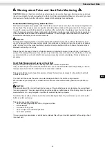
Heart Rate Controlled Programs (HRC)

These programs are heart-rate-controlled exercise programs. The user specifies a desired target heart rate. 

This is permanently compared by the cockpit with the actual heart rate of the user. If the actual heart rate is 

lower than the desired target heart rate, the cockpit automatically increases the resistance. If the value is higher, 

the cockpit automatically reduces the resistance.

The main requirement for these programs is a permanent and accurate transmission of heart rate values. For 

this reason, these programs can only be used together with an uncoded heart rate chest belt which is available 

as an extra accessory. It is not possible to use these programs with hand-pulse sensors. Please also read the 

chapter “Heart rate measurement” in this manual.

Step 1: Selecting a Program

Turn on the exerciser. The upper part of the display flashes “M”. Select the heart symbol by turning the control 

knob clockwise / anti-clockwise and confirm your selection by pressing it. 

Step 2: Age Input

The display will show the letter “A” and the value “25” will flash, enter your age from 1 to 99 years by turning the 

control knob clockwise / anticlockwise, and confirm your entry by pressing it. 

Step 3: Selecting the HRC Mode 

By pressing the UP & DOWN keys, you can now choose between the following HRC modes: 

50% 

– Training with a target heart rate of 50% of the maximum heart rate

75% 

– Training with a target heart rate of 75% of the maximum heart rate

90% 

– Training with a target heart rate of 90% of the maximum heart rate

TA

 – Training with an individual target heart rate

Please also read the section “Warning for Pulse & Heart Rate Measurement” in this manual. 

Select the desired modes by turning the control knob clockwise / anti-clockwise.

If you select 55%, 75% or 90%, the corresponding target heart rate will be displayed directly. Confirm your 

selection by pressing the control knob. 

To train with an individual target heart rate, select the TA mode by turning the control knob clockwise / anti-clock

-

wise and confirm the selection by pressing it. The “PULSE” window will flash “100.” Now enter the desired target 

heart rate between 30 and 230 heartbeats / minute again by turning the control knob clockwise / anticlockwise 

and confirm your entry by pressing it.

Cockpit

Summary of Contents for CX 5.1

Page 1: ...ENG Cross Trainer MAXXUS CX 5 1 I N S TA L L AT I O N O P E R AT I N G M A N U A L...

Page 2: ...d Drawing 27 Parts List 28 FAQ 29 Recommended Accessories 29 Warranty 30 Service Contract 31 2019 MAXXUS Group GmbH Co KG All rights reserved All rights reserved This publication may not be reproduced...

Page 3: ...always mounted on a level clean surface is Unevenness in the ground must be removed or compensated To protect delicate floors such as wood lamina tiles etc and from damage such as scratches it is rec...

Page 4: ...ers for Pendulum Handlebars C07 C08 Covers for Handlebar Shaft Overview of the Device Scope of Delivery Box A Pendulum handlebar Hand pulse sensors Fixed Handlebars Handlebar Stem Bottle holder Pedal...

Page 5: ...Washer B33 5 16 x20x2 0 4 pcs 3 Allen Screw B41 M8x25mm 2 pcs 4 Hexagonal Screw B32 M8x16 4 pcs 5 Washer B21 3 8 x20x2 0 4 pcs 6 Curved Washer B28 M8x20x1 5 4 pcs 7 Carriage bolt B28 M8x50mm 4 pcs 8 T...

Page 6: ...s level clean and free from obstructions Carry out the assembly with 2 people Only after the installation of your training device has been completed can training be started Step 1 Assembling the Stand...

Page 7: ...x20 9 WARNING Make sure that the cables do not get pinched or damaged when you are assembling the handlebar stem Step 4 Assembling the Fixed Handlebars Pass the cable protruding out of the handlebar s...

Page 8: ...cating both transverse axles on the handlebar stem with a multi purpose grease before assembling the pendulum tubes This will optimise the smooth running of the pendulum tubes Fig 1 Right Wrong Step 5...

Page 9: ...tube A04 The right and left handlebars are each labelled and so easy to identify Fix each of the handlebars with two carriage bolts M850 7 two curved washers M8 6 and two lock nuts M8 14 Step 7 Assemb...

Page 10: ...ndulum handlebar covers C17 C18 using two tapping screws M5x16 8 on each to the left and right pendulum handlebars A03 left A04 right as shown in the diagram Step 9 Assembling the Pedal Covers Now pre...

Page 11: ...g device upwards until the main weight of the training device rests on the transport rollers Now you can simply push the device on the transport rollers into the required position Always make sure tha...

Page 12: ...s The top of the sliding tubes must be cleaned and lubricated regularly Clean the sliding tubes with a damp cloth and some liquid hand soap or detergent For professional cleaning we recommend the MAXX...

Page 13: ...amage the electronic components of the device for which the manufacturer assumes no liability Always connect the power cable to the exerciser before connecting it to a power outlet If you want to disc...

Page 14: ...ulse or heart rate display PULSE When using the hand pulse sensors displays the current pulse value in beats per minute When using an optional transmitter chest belt not included displays the current...

Page 15: ...n the display shows U1 There are four user profiles available U1 U4 These are fixed i e the user data is stored permanently Selecting a User Profile Turn the control knob to select the desired user pr...

Page 16: ...y the training distance enter it by turning the control knob clockwise anticlockwise You can set the training distance from 1 0 to 99 0 kilometres in 1 kilo metre increments Confirm your selection by...

Page 17: ...g Level Select the desired training level by turning the control knob clockwise anti clockwise Confirm your selection by pressing the control knob Step 3 Setting the Training Time The value in the TIM...

Page 18: ...t rate This is permanently compared by the cockpit with the actual heart rate of the user If the actual heart rate is lower than the desired target heart rate the cockpit automatically increases the r...

Page 19: ...grams WATT In this type of training the power in watts selected by the user is kept constant permanently by the cockpit The user s output watts results from the current resistance level and the curren...

Page 20: ...and the BMI of the user Press the FAT key The currently selected user profile is dis played as U1 If the wrong user profile has been selected press the RESET key and select the correct user profile Th...

Page 21: ...oth function on your smartphone or tablet PC Open the iC Training App Step 3 Select GET STARTED in the top right of the menu Then select the required training type such as QUICK START Step 4 A list of...

Page 22: ...25 carbohydrate and 5 protein Fat burning target zone 60 to 70 of the maximum heart rate This training zone is suitable for athletes and sports people who aim to lose weight Training in this zone the...

Page 23: ...several people If the display of the pulse does not work only in individual cases the device is not defective In this case we recommend the use of a chest belt to achieve a permanently correct pulse d...

Page 24: ...o not just get off your training device immediately the training session is finished Like with the warm up stage you should continue for 3 5 minutes at minimum resistance to cool down After training y...

Page 25: ...nce most people have training goals such as weight reduction cardiac exercise training improvement of physical con dition stress reduction etc to strive for training intensity to meet these goals shou...

Page 26: ...ubt seek advice from your local government office or county council as to where you can dispose of the device properly and in an environmentally sound manner Batteries Rechargeable Batteries if applic...

Page 27: ...27 ENG Exploded Drawing...

Page 28: ...Action Arm Pivot 2 B32 M8 Hex Head Screw 6 B33 5 16 Washer 8 B34 M10 Hex Head Screw 2 B35 M8 Allen Key Screw 4 B36 M3 Sheet Metal Screw 2 B37 3 16 Sheet Metal Screw 1 B38 M3 Sheet Metal Screw 2 Part...

Page 29: ...device is standing straight and flat on the ground If not re adjust the foot stands Check if the screws at the articu lated joint between the pendulum tubes and the pedal arms are tightened securely M...

Page 30: ...eriod for your training device starts on the date of purchase and applies solely to products which were purchased directly from the MAXXUS Group GmbH Co KG or one of the MAXXUS Group GmbH Co KG direct...

Page 31: ...t must be completed Fault Description Please enter a short description of the error as precisely as possible below For example when where and how does the error occur Frequency after which period at w...

Page 32: ...32 Maxxus Group GmbH Co KG Zeppelinstr 2 D 64331 Weiterstadt Germany E Mail info maxxus com www maxxus com...

Reviews: