maxon motor
Operating Instructions
4-Q-DC Servo Control LSC 30/2
8 EMC-compliant
installation
Power supply (+V
CC
- Power Gnd)
•
No shielding normally required.
•
Star point-shaped wiring if several amplifiers are supplied by the same power supply.
Motor cable
•
No shielding normally required.
Encoder cable
•
Although the LSC 30/2 does not have a line receiver, using an encoder with a line driver is
recommended as this improves interference resistance.
•
Use cable shielding in electromagnetically harsh environment.
•
Connect shielding on both sides (LSC housing).
•
Use separate cable.
Analogue signals (Set, Tacho, Vaux)
•
No shielding normally required.
•
Use cable shielding with analogue signals with small signal level and electromagnetically
harsh environment.
•
Normally connect shielding on both sides (LSC housing). Place shielding on one side if
there are 50/60 Hz interference problems.
Digital signals (Disable, Ready)
•
No
shielding
necessary.
In practical terms, only the complete equipment, comprising all individual components
(motor, amplifier, power supply unit, EMC filter, cabling etc.) can undergo an EMC test to
ensure interference-free CE-approved operation.
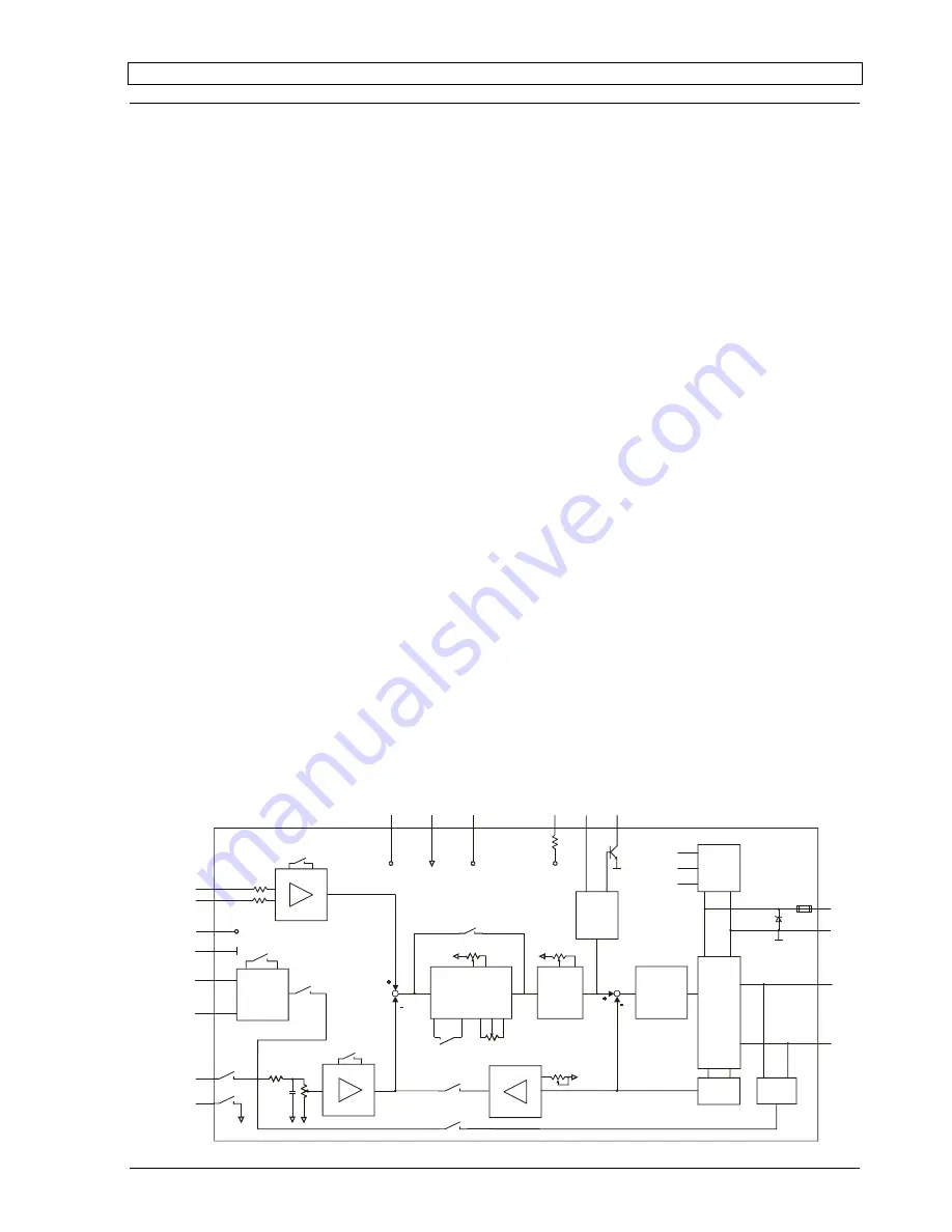
9 Block Diagram
Linear
Power
Stage
+Motor
-Motor
Gnd
+Vcc 12-30VDC
Current
Detector
Voltage
Detector
DIP6
+5V
+3.9V
-3.9V
Supply
Dis IN Ready
F/V Converter
+Venc
Gnd
Ch A
Ch B
DIP8
+5V/80mA
DIP2
DIP3
+Vcc
Dis +V
Control &
Protection
Logic
+Vaux
-Vaux
Sig Gnd
+3.9V/2mA
-3.9V/2mA
P2 IxR
P4 I max
Current
Limit
P3 Offset
DIP7
PI
Speed Control
DIP9
P5 gain
PI
Current
Control
-Set value
+Set value
DIP10
P1 n max
+Tacho
DIP5
DIP4
-Tacho
DIP1
June 2010 Edition / Subject to change
maxon motor control
13


