


T
ABLE
8: UART C
HANNEL
[7:0] I
NTERRUPT
C
LEARING
Wake-up Indicator is cleared by reading the INT0 register.
RXRDY and RXRDY Time-out is cleared by reading data in the RX FIFO.
RX Line Status interrupt clears after reading the LSR register that is in the UART channel register set.
TXRDY interrupt clears after reading ISR register that is in the UART channel register set.
Modem Status Register interrupt clears after reading MSR register that is in the UART channel register set.
RTS/CTS or DTR/DSR delta interrupt clears after reading MSR register that is in the UART channel register set.
Xoff/Xon delta and special character detect interrupt clears after reading the ISR register that is in the UART channel
register set.
TIMER Time-out interrupt clears after reading the TIMERCNTL register that is in the Device Configuration register set.
MPIO interrupt clears after reading the MPIOLVL register that is in the Device Configuration register set.
XR17V358
23
REV. 1.0.6
HIGH PERFORMANCE OCTAL PCI EXPRESS UART
1.4.2
General Purpose 16-bit Timer/Counter [TIMERMSB, TIMELSB, TIMER, TIMECNTL] (
DEFAULT
0
X
XX-XX-00-00)
The XR17V358 has a general purpose 16-bit timer/counter. The internal 125 MHz clock (master mode) or 62.5
MHz clock (slave mode) or the external clock at the TMRCK input pin can be selected as the clock source for
the timer/counter. The timer can be set to be a single-shot for a one-time event or re-triggerable for a periodic
signal. An interrupt may be generated when the timer times out and will show up as a Channel 0 interrupt (see
). It is controlled through 4 configuration registers [TIMERCNTL, TIMER, TIMELSB, TIMERMSB]. The
TIMERCNTL register provides the Timer commands such as start/stop, as shown in
below. The time-
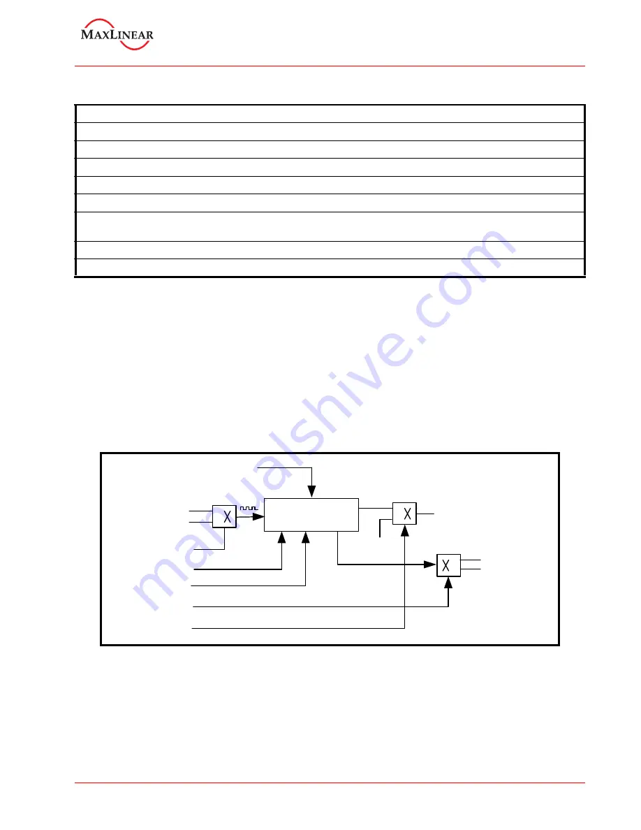
out output of the Timer can also be optionally routed to the MPIO[0] pin. The block diagram of the Timer/
Counter circuit is shown below:
F
IGURE
6. T
IMER
/C
OUNTER
CIRCUIT
Timer Interrupt
Timer
Output
MPIOLVL[0]
0
1
0
1
Timer Interrupt
No Interrupt
MPIO[0]
TMRCK
125MHz/62.5MHz
TIMERCNTL
COMMANDS
16-Bit
Timer/Counter
Start/Stop
Timer Interrupt Enable/ Disable
Single shot/Re-triggerable
TIMERMSB and TIMERLSB
(16-bit Value)
0
1
Clock Select
Route/De-route to MPIO[0]
TIMERMSB [31:24] and TIMERLSB [23:16] registers
The concatenation of the 8-bit registers TIMERMSB and TIMERLSB forms a 16-bit value which decides the
time-out period of the Timer, per the following equation:
Timer output frequency = Timer input clock / 16-bit Timer value
The least-significant bit of the timer is being bit [0] of the TIMERLSB with most-significant-bit being bit [7] in
TIMERMSB. Notice that these registers do not hold the current counter value when read. Default value is zero
(timer disabled) upon powerup and reset. The ’Reset Timer’ command does not have any effect on this
register.