i-SHWAK V4
Inverter air/water chillers and heat pumps with wall-mounted indoor unit and remote condensing outdoor unit
22
x
check if the work is being done well by evaluating the rise time by mean of pressure gauge that integrated in the vacuum
pump.
x
release the refrigerant contained in the moto-condensing unit by opening the gas/liquid valves (see Paragraph 8.4.2.3)
x
add or take out a proper amount of refrigerant as indicated in the paragraph 14.2 see note (5).
x
check if there is no refrigerant leakage;
x
cover the connections with insulating material.
Do not put both pipes in the same protecting sheath, in order to ensure the correct operation of the plant.
Please refer to section 14 for the minimum and maximum lengths, and possible differences in level.
Do not carry out the connections by using ordinary hydraulic pipes that might contain inside themselves residues of
chips, dirt, or water which can damage the components of the unit and disturbs the correct operation of the
equipment.
Use only specific refrigeration copper pipes that should be provided clean and sealed at the ends.
Use only pipes with correct dimensions of diameters; refer to the table of the technical data in the chapter 14.
Cut the pipes with wheel pipes cutter, clutch slowly paying attention for not to crush the pipes when using the tool.
Never use an ordinary hacksaw because shavings could go into the pipe and then circulate in the system which can
seriously damage the components.
After cutting the pipe, please seal immediately the opening on both ends of the roll and cut pipe.
The equipment does not require any preloaded refrigerant lines.
The refrigerant pipes should be straight as possible and the necessary bends must have radius more than 300mm.
Plug the opening on the ends of the pipes before inserting them through the hole in the wall.
The refrigerant piping and joints must be thermally insulated to prevent heat loses.
You should avoid the introduction of non-condensable gases (air) into the circuit, otherwise, the pressure becomes
high during operation with the risk of system breaking.
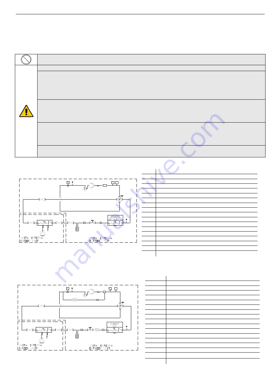
8.6.1
Refrigerant diagram for i-SHWAK V4 06 e 08 models
IN
OUT
DT
ST
LP
HP
4WV
LR
EEV
FL
FL
C
CLS
Pr
PV
PV
MF
SE
M
P
C
COMPRESSOR
CLS
COMPRESSOR LIQUID SEPARATOR
ST
COMPRESSOR INLET TEMPERATURE
DT
COMPRESSOR OUTLET TEMPERATURE
HP
HIGH PRESSURE TRANSDUCER
Pr
HIGH PRESSURE FLOW SWITCH
LP
LOW PRESSURE TRANSDUCER
LS
LIQUID SEPARATOR (only for the model 09)
4WV
VALVE FO INVERTING CYCLE
LR
LIQUID RECEIVER
EEV
ELECTRONIC EXPANSION VALVE
FL
FILTER
M
AXIAL FAN
MF
MUFFLER SILENCER
SE
OUTDOOR AIR TEMPERATURE SENSOR
P
CIRCULATOR ON BOARD UNIT
IN
WATER INLET TEMPERATURE
OUT
WATER OUTLET TEMPERATURE
8.6.2
Refrigerant diagram for i-SHWAK V4 10 e 12 models
DT
OS
ST
LP
HP
4WV
LR
EEV
FL
FL
FL
C
CLS
Pr
Pr
PV
PV
CP
CP
SE
M
IN
OUT
P
C
COMPRESSOR
CLS
COMPRESSOR LIQUID SEPARATOR
OS
OIL SEPARATOR (only for the models 12 and 15)
ST
COMPRESSOR INLET TEMPERATURE
DT
COMPRESSOR OUTLET TEMPERATURE
HP
HIGH PRESSURE TRANSDUCER
Pr
HIGH PRESSURE FLOW SWITCH
LP
LOW PRESSURE TRANSDUCER
4WV
VALVE FOR INVERTING CYCLE
LR
LIQUID RECEIVER
EEV
ELECTRONIC EXPANSION VALVE
FL
FILTER
M
AXIAL FAN
SE
OUTDOOR AIR TEMPERATURE
P
CIRCULATOR ON BOARD UNIT
IN
WATER INLET TEMPERATURE
OUT
WATER OUTLET TEMPERATURE
CP
CAPILLARY


