DBF01O04.docx
(MAVIG #7111730)
page 1 of 22
Assembly Instructions -Ceiling
Substructure
GD60D012
GD60D022
GD60D032
Page 1: ...DBF01O04 docx MAVIG 7111730 page 1 of 22 Assembly Instructions Ceiling Substructure GD60D012 GD60D022 GD60D032 ...
Page 2: ...ensure that the contents of this manual do not contain any errors or omissions Nevertheless MAVIG assumes no liability with regard to the contents of this document and specifically disclaims any implied warranties Amendments MAVIG products are subject to continuous development MAVIG reserves the right to make changes to the manual packaging equipment or technical specifications without prior notif...
Page 3: ...d 8 2 2 Intended Use 9 3 Installation 10 3 1 Secure Ceiling Anchorage 11 3 2 Fastening the Ceiling Plate 12 3 3 Option to Fixate a Connection Plate 13 3 4 Installation of the Middle and Interface Plates 14 3 4 1 GD60D012 15 3 4 2 GD60D022 16 3 4 3 GD60D032 18 3 5 Fastening of an Assembly Aid 20 4 Safe Disposal 20 5 Technical Data 21 ...
Page 4: ...ient or user Read and make sure you understand all warnings before installing the system CAUTION This indicates that the information is provided as a precautionary measure Precautionary measures refer to circumstances which could result in damage to the device or impair its proper functioning You must read and understand the precautions before installing the system NOTE This provides advice on the...
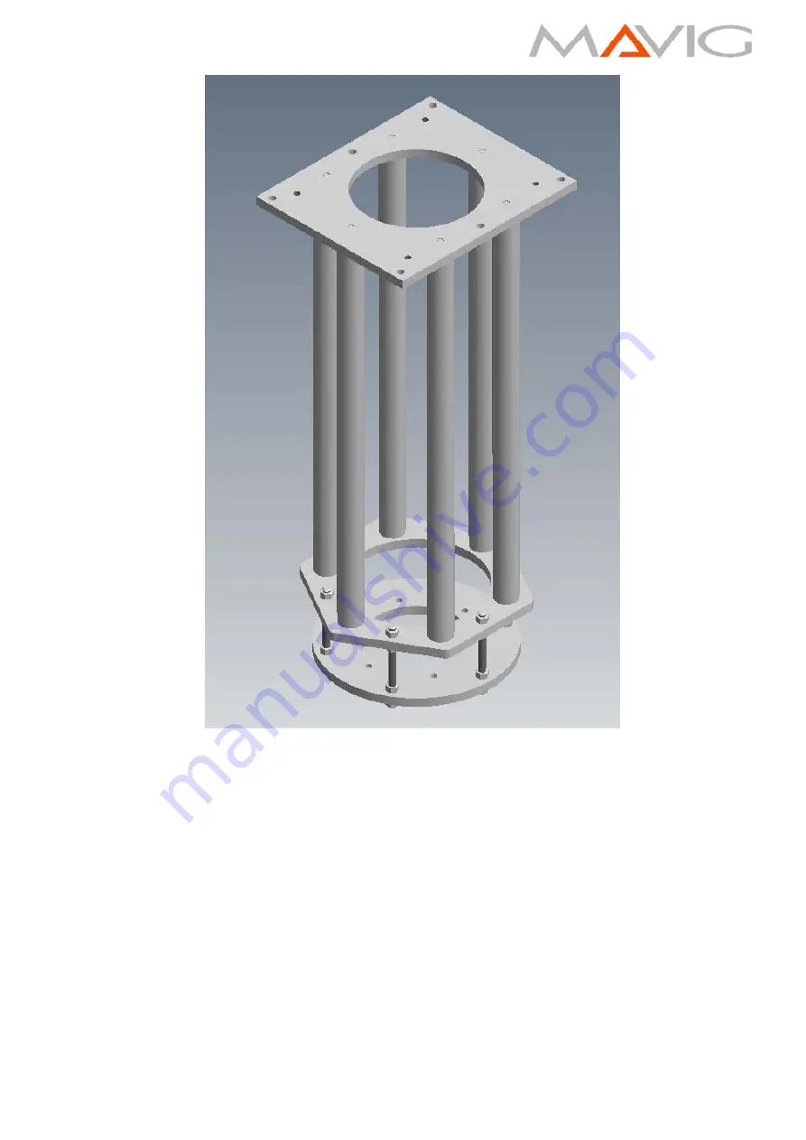
Page 5: ...SCOPE OF DELIVERY The ceiling substructure is available in three different length variations see Fig 1 MAVIG purchase numbers Short variation GD60D012 Medium variation GD60D022 Long variation GD60D032 GD60D032 max 79kg GD60D022 max 59kg GD60D012 max 41kg Fig 1 ...
Page 6: ... 940mm 12x DIN 9021 washers only GD60D032 18x ISO4032 M16 class 8 hexagon nuts 4 Middle Plate weight approx 12 5kg Fig 4 5 False Ceiling 6 Interface Plate weight approx 15 kg Fig 5 6x DIN 975 M16 class 8 8 threaded rods Length 195 mm 24x ISO4032 M16 class 8 hexagon nuts 18x for GD60D012 7 Anchor point as assembling aid for e g monitors 1x DIN 580 M12 eye bolt 1x DIN9021 13x37x3 washer 8 Anchor poi...
Page 7: ...DBF01O04 docx MAVIG 7111730 page 7 of 22 Ceiling plate Fig 3 Middle plate Fig 4 ...
Page 8: ...ate Fig 5 2 1 TOOLS REQUIRED Torque wrench for 200 Nm 3 with socket and open end wrench SW 24 mm Metal saw Vice with protective braces e g Aluminum Measuring tape Spirit level accuracy 1mm m digital spirit level strongly recommended Paint Seal Loctite 270 ...
Page 9: ...etween the solid ceiling and the false ceiling for ceiling mounted medical devices supported by suspension arms in the operating theatre intensive care and general medical rooms The length of the substructure can be adapted to a specific needed length The ceiling substructure is designed to withstand long term service The ceiling substructure must not be used in rooms in which flammable mixtures c...
Page 10: ...jury Sharp edges may be exposed during the assembly of components Work with caution If applicable wear protective gloves Assembly of the systems As pointed out by MAVIG in these assembly instructions the ceiling must be checked for sufficient stability by a structural engineer before assembly and the assembly must occur under the guidance of the respective construction supervision If these instruc...
Page 11: ... The screws used to attach the system to the ceiling are not part of the system The substructure shall be fastened to the ceiling with following specifications o The maximum axial load per bolt will not exceed 7210N o The maximum Shear load per bolt will not exceed 957N o The maximum pullout force shall be calculated in accordance with local building codes and it is part of structural analysis don...
Page 12: ...ing plate to the ceiling utilizing the six holes with diameter 17mm at 360mm x 451mm The ceiling plate can be fastened to the ceiling using six suitable screws These screws must be dimensioned according to the conditions of the ceiling and provided by the customer Make sure that the plate is sitting flush to the ceiling in order to ensure optimum load distribution This can be checked by use of a s...
Page 13: ...e of c Install 2 additional hexagon nuts on the 2 neighboring threaded rods where the connection plate needs to be fixated red arrows below The additional nuts don t need to be tightenend Fig 9 In chapters 3 4 2 page 16 and 3 4 3 page 18 The value of a has to be 155mm Install 2 additional hexagon nuts on the 2 neighboring threaded rods where the connection plate needs to be fixated red arrows belo...
Page 14: ...fter tightening every threaded rod has to protrude min 5mm from the nut CAUTION damage to equipment Make sure that the length of the threaded rods are not too long The threaded rods may protrude max 36mm from below the nut of the interface plate see Fig 11 NOTE Every M16 hexagon nut including the ceiling plate securing nuts must be tightened with 200 Nm 3 torque and secured with Loctite 270 After ...
Page 15: ... ends of the threaded rods Screw the uncut ends of the threaded rods fully into the ceiling plate 3 Secure each threaded rod with the preassembled hexagon nut to the ceiling plate Make sure there s still enough Loctite 270 on the rods for the nuts Fig 13 Apply Loctite 270 to the lower ends of the threaded rods Push the interface plate 4 up to the required height on the threaded rods and secure fro...
Page 16: ...ods need to be cut Calculating the length of the threaded rods L1 L2 a min 145mm max 155mm b min 35mm max 435mm c distance from concrete ceiling to lower face of false ceiling must be measured IF c 175mm up to 210mm Cut L1 to 95mm Tolerance 10mm 0mm Cut L2 to c 15mm Tolerance 10mm 0mm final length L2 will be from 160mm to 195mm IF c 210mm up to 610mm Cut L1 c 115mm Tolerance 10mm 0mm final length ...
Page 17: ...e plate If needed cut each of the short M16 threaded rods 5 to the length L2 at one end only Burr max 2mm the cut ends of the threaded rods Make sure that all threads are not damaged or dirty Screw hexagon nuts 2 ca 5cm onto both ends of each threaded rod Apply Loctite 270 to both ends of the threaded rods Insert the threaded rods to the middle plate 4 and tighten them from above and below with a ...
Page 18: ... the false ceiling is 610mm 1115mm Calculating the length of the threaded rod L1 and the tube b a min 145mm max 155mm b distance between ceiling plate and middle plate length of the tube c distance from concrete ceiling to lower face of false ceiling must be measured Cut L1 to c 115mm Tolerance 10mm 0mm Cut b to c 175mm Tolerance 1mm 0 5 Fig 15 ...
Page 19: ...on the middle plate The hexagon nuts 9 are used to secure the washers 2 in a position near the middle plate They can t be tightened Make sure that even after tightening there will be min 5mm space between the lower washers and the nuts 9 Tighten the hexagon nuts 3 to the middle plate from below Install the interface plate Make sure that all short M16 threaded rods 7 are not damaged or dirty Screw ...
Page 20: ...e disposed of in accordance with the nationally applicable provisions at an appropriate recycling facility for electrical and electronic equipment You may also return the system device to MAVIG for disposal If you have any questions please contact us at e Mail info mavig com Tel 49 0 89 420 96 0 RoHS Conformity The support arm system meets the requirements of Directive 2011 65 EU RohS Restriction ...
Page 21: ...ntinuous operation Classification In accordance with European Guideline 93 42 EEC Class I medical product Approval of the Relevant Standard Version The ceiling substructures is tested in accordance with UL 60601 1 2012 CE Conformance The ceiling substructure complies with the provisions of Directive 93 42 EEC Medical Device Guidelines CE SYMBOL MAVIG GmbH Stahlgruberring 5 81829 Munich Germany ...
Page 22: ...DBF01O04 docx MAVIG 7111730 page 22 of 22 ...