background image


25

Floppy 3 Mode
Support

Floppy 3 Mode refers to a 3.5” diskette with a
capacity of 1.2 MB. This diskette is sometimes
used in Japan

Video

This item defines the video mode of your system.
Set it to EGA/VGA.

Halt On

This item determines what kind of errors are
sufficient to halt the system.

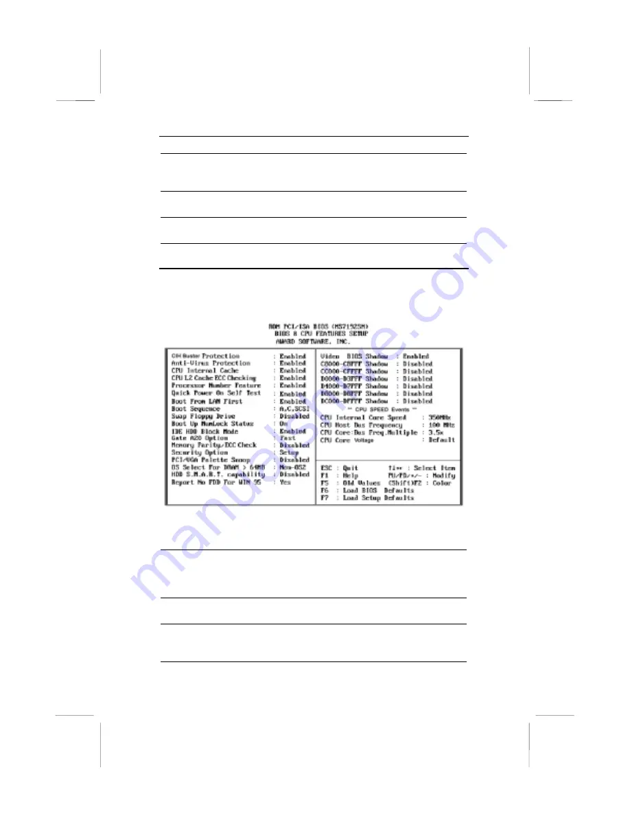
BIOS & CPU Features Setup Page

Use this page to set more advanced information about your system.
Take some care with this page. Making changes can affect the
operation of your computer.

CIH Buster

Protection

Enable this item so that your system BIOS is
protected from CIH virus which attack the BIOS
of your system.

Anti-Virus
protection

Enable this item so that your system is protected
from some viruses that attack the partition table
of your hard disk. Disable this item if you are
installing a new OS.

CPU Internal
Cache

All the processors supported by this system have
internal level-1 cache so leave this item enabled.

CPU L2 Cache
ECC Checking

If you enable this item, the system will carry out
error checking an any level 2 (external) cache
memory that is supplied with the CPU.

Summary of Contents for MS7192SM

Page 1: ...y any person of such revision or changes Trademarks IBM VGA OS 2 and PS 2 are registered trademarks of International Business Machines Intel Pentium Pentium II Pentium III MMX and Celeron are register...

Page 2: ...ion between the equipment and the receiver Connect the equipment onto an outlet on a circuit different from that to which the receiver is connected Consult the dealer or an experienced radio TV techni...

Page 3: ...tic Electricity Precautions 6 Chapter 2 Mainboard Installation 7 Mainboard Components 8 I O Ports 9 Install the Processor 9 Install Memory 12 Set the Jumpers 13 Jumper JP1 Clear CMOS Memory 13 Jumper...

Page 4: ...p Page 27 Power Management Setup Page 29 PNP PCI Configuration Page 31 Load BIOS Defaults 32 Load Optimum Settings 32 Integrated Peripherals Page 33 Password Settings 35 Change or Remove the Password...

Page 5: ...A6 Learning how to use Corel WordPerfect Suite 8 A9 Support and Services A13 Appendix B Gamut B1 Introduction B2 Before Installing B3 Installation B4 Produce MP3 file Use CD Cashier B5 Play MP3 file...

Page 6: ...his mainboard The mainboard is highly integrated and includes a built in PCI 3D Sound System A 56K V 90 Fax Modem DAA module is also shipped with the mainboard In addition the mainboard has a full set...

Page 7: ...GA Celeron 66 MHz bus All processors configured by CPU Plug and Play Memory Support Three DIMM slots for 3V SDRAM 168 pin memory modules Support for 66 MHz and 100 MHz memory bus Supports 1 bit ECC Er...

Page 8: ...in 32 ohm earphone buffer and 3D surround Provides MPU 401 Game MIDI port and legacy Sound Blaster 16 support Downloadable Wave table Synthesizer supports Direct Music Digital Audio Interface with 24...

Page 9: ...or automatic CPU and board configuration Supports plug and play configuration of peripheral devices and expansion cards Built in virus protection using Trend s ChipAwayVirus which ensures that the ent...

Page 10: ...lot 1 cartridge holder This User s guide IDE cable Floppy diskette drive cable V 90 Fax Modem DAA module Support software CD ROM Optional Accessories You can purchase the following optional accessorie...

Page 11: ...ap frequently discharge any static electricity by touching the bare metal of the system chassis 4 Handle the mainboard carefully by the edges Avoid touching the components unless it is absolutely nece...

Page 12: ...more memory modules Verify that any jumpers or switches are at the correct setting Install the mainboard in the system chassis Install any other devices and make the appropriate connections to the mai...

Page 13: ...ur mainboard Slot 1 JP2 ATX1 Socket 370 CD1 CD2 SPDIF1 SIR1 AGP1 Sideband1 PCI1 PCI2 PCI3 PCI4 ISA1 ISA2 CPUFAN1 JP4 DIMM1 DIMM2 DIMM3 FDD1 IDE1 IDE2 PANEL CASEFAN1 JP1 WOM1 WOL1 JP7 J2 J1 Note Any ju...

Page 14: ...ew Celeron processor which is shipped in a PPGA Plastic Pin Grid Array package To ensure reliability make sure that your PPGA Celeron processor is fitted with a heatsink cooling fan assembly You can i...

Page 15: ...Celeron 400 Slot 1 66 SEPP Celeron 366 Slot 1 66 SEPP Celeron 333 Slot 1 66 SEPP Celeron 300A Slot 1 66 SEPP Celeron 300 Slot 1 66 SEPP Celeron 266 Slot 1 66 PPGA Celeron 533 Socket 370 66 PPGA Celer...

Page 16: ...h so that it only fits into the Slot 1 in the correct way 4 Locate the cooling fan power supply CPUFAN1 Connect the cable from the processor cartridge cooling fan to FAN1 5 On this mainboard you can c...

Page 17: ...f the Celeron processor is installed with a cooling fan assembly connect the cable from the fan to the CPU fan power connector CPUFAN1 Install Memory The mainboard has three DIMM slots which can be in...

Page 18: ...sets of pins which can be connected together with jumper caps The jumper caps change the way the mainboard operates by changing the electronic circuits on the mainboard If a jumper cap connects two p...

Page 19: ...ct if the installed processor requires a system bus speed of 66 MHz or 100 MHz If you set this jumper to Force 100 MHz the system will always use a 100 MHz bus even for processors that are rated to ru...

Page 20: ...r cable from the power supply unit to the power connector ATX1 on the mainboard If the system chassis is installed with a cooling fan connect the cable from the cooling fan to the chassis fan power co...

Page 21: ...a red stripe on the pin 1 side of the cable Fax Modem DAA Module The Fax Modem DAA module plugs directly into the mainboard adjacent to an expansion slot in the system chassis When you remove the bla...

Page 22: ...for this bracket 2 Plug the cable from the bracket into the SPDIF1 header 3 In the system chassis remove a blanking plate from one of the expansion slots and install the extension bracket in the slot...

Page 23: ...the port to the header SIR1 and then secure the port to an appropriate place in your system chassis Install Other Devices Install and connect any other devices in the system following the steps below...

Page 24: ...system power unit Use the cable provided to connect the device s to the Primary IDE channel connector IDE1 on the mainboard If you want to install more IDE devices you can purchase a second IDE cable...

Page 25: ...nsion Card 1 Locate the AGP PCI or ISA slot on the mainboard 2 Remove the blanking plate from the appropriate expansion slot on the system chassis 3 Install the edge connector of the expansion card in...

Page 26: ...d a fax modem card connect the fax modem to the wake on modem connector WOM1 You can then use the setup utility to program your computer to resume from a power saving mode whenever there is an incomin...

Page 27: ...s smoothly If the information in the setup utility is incorrect it may cause your system to malfunction It can even stop your computer from booting properly If this happens you can use the clear CMOS...

Page 28: ...p utility press the Escape key Hold down the Shift key and press F2 to cycle through the optional color schemes of the setup utility Some of the options on the Main Menu page lead to tables of items w...

Page 29: ...s show the characteristics of any hard disk drives on the four available IDE channels Note that SCSI hard disk drives do not appear here You can automatically install most modern hard disks using the...

Page 30: ...ffect the operation of your computer CIH Buster Protection Enable this item so that your system BIOS is protected from CIH virus which attack the BIOS of your system Anti Virus protection Enable this...

Page 31: ...tem if your IDE hard disk drive supports block mode data transfers Gate A20 Option This item determines how the system runs legacy software written for early X86 processors Leave this item at the defa...

Page 32: ...ency CPU Core Bus Freq Multiple If you set the item above CPU Internal Core Speed to Manual you can use these two items to set the system bus speed and the CPU clock rate After you set the CPU Host Bu...

Page 33: ...ult value Concurrent PCI Host This item allows concurrent operation for the system PCI bus We recommend that you leave this item at the default value System BIOS Cacheable Video BIOS Cacheable These i...

Page 34: ...ax Saving the system powerdown timeouts are short If you set to Min Saving the powerdown timeouts are longer If you set to User Define you can set the powerdown timeouts manually using the items below...

Page 35: ...de If the time passes with no activity the system enters suspend mode VGA If this item is enabled any video activity will resume the system from a power saving mode or a software power down LPT COM If...

Page 36: ...to IRQ15 These items are a list of the system interrupts and a description of the devices which use them If you disable the interrupt it has no effect on the system power management If you set an ite...

Page 37: ...item is enabled an IRQ will be assigned to the PCI VGA graphics system Onboard PCI Audio Modem Use these items to enabled or disabled the onboard sound system and fax modem Load BIOS Defaults If you s...

Page 38: ...n IDE device IDE Primary Secondary Master Slave PIO The primary and secondary IDE channels can each support a Master and Slave device Use these items to enable a Programmable Input Output mode for eac...

Page 39: ...UART Mode Select This item defines the operation of serial port 2 In the Normal setting serial port 2 is assigned to the external COM2 connector If you have installed an optional infrared port you mus...

Page 40: ...tion Press Enter after you have retyped it correctly The password is required at boot time or when the user enters the setup utility Change or Remove the Password Highlight the items and type in the c...

Page 41: ...xit dialog box appears press Y to save and exit or press N to return to the setup main menu Exit Without Saving Highlight this item and press Enter to discard any changes that you have made in the set...

Page 42: ...are properly installed choose the MULTIMEDIA icon in the CONTROL PANEL when you need to use the Software Wave Table drivers as a MIDI output device Select the MIDI page and click on C media SoftMidi S...

Page 43: ...speaker system If you are running applications which use the DirectSound 3D or A3D audio interface your system can simulate realistic 3D sound through a 4 speaker setup Follow the steps below to inst...

Page 44: ...hardware conflicts DO NOT enable this option when the Line in Rear jack is connected with a line in device While the 4 speakers mode is enabled turn on off the output of the front speakers and adjust...

Reviews: