background image

Rev. 

Descrizione 

Redatto/Gestito 

Approvato 

Cod.Ident. 

Pagine 

Data Em. 

0.6 

Manuale Istruzioni 

GN 

UTEC 

B041.M01.EN 

36

/47 

07/2014 


Example file stored 

 [DATA] 
Test: [Description] 
Test type: Giratory compactor test 
Test date: 1/16/2013 
Test time: 12:19:06 PM 
 
Internal angle: 1.160 ° 
Load: 10.600 kN 
Speed: 30.000 Rpm 
Gyrations: 18  
Mould:  Ø150 
Weight: 5.000 kg 
Stop mode:  Gyration 
 
[RESULTS] 
END TEST STOP 
Gyrations: 18 
Height: 117.119 mm 
Density: 2415.853 kg/m³ 
 
[GRAPHINFO] 
Axis0=2;1.000;18.000;0 
Axis1=1;1.100;1.200;0 
Axis2=1;10.200;11.000;0 
Axis3=1;117.100;117.200;255 
Axis4=1;2415.200;2416.100;65280 
Graph1=0;3 
Graph2=0;4 


[GRAPH] 
Gyrations 

Angle [°] 

Load [kN] 

Height [mm] 

Density 

[kg/m³] 


1.139 


10.635   

117.130  

2415.629 


1.134 


10.604   

117.115  

2415.930 


1.138 


10.613   

117.108  

2416.077 


1.138 


10.608   

117.147  

2415.277 


1.140 


10.604   

117.150  

2415.232 


1.139 


10.617   

117.149  

2415.240 


1.138 


10.610   

117.147  

2415.283 


1.136 


10.600   

117.147  

2415.266 


1.137 


10.617   

117.150  

2415.215 

10 


1.137 


10.609   

117.147  

2415.266 

11 


1.137 


10.611   

117.149  

2415.240 

12 


1.137 


10.599   

117.148  

2415.249 

13 


1.135 


10.616   

117.111  

2416.023 

14 


1.136 


10.614   

117.116  

2415.921 

15 


1.135 


10.616   

117.117  

2415.887 

16 


1.134 


10.602   

117.118  

2415.870 

17 


1.135 


10.615   

117.116  

2415.913 

18 


1.133 


10.594   

117.119  

2415.853 

 
[CHECKSUM] 
0001054D


Example of print to USB printer


Summary of Contents for B041

Page 1: ...PERATE THIS APPLIANCE BEFORE READING AND LEARNING THIS MANUAL IN ALL ITS PARTS USERS MACHINE MANUFACTURERS DRAUGHTSMEN OPERATORS MAINTENANCE WORKERS REV DESCRIZIONE REDATTO GESTITO APPROVATO COD IDENT PAGINE DATA EMIS 06 Manuale Istruzioni GN UTEC B041 M01 EN 48 07 2014 ...

Page 2: ...NSTRUCTIONS 4 1 Location 4 2 Handling and movement 4 3 Assembling procedure 4 4 Electrical connection 4 5 Pneumatic connection Chapter 5 MAN COMMAND INTERFACE 5 1 Workplace 5 2 Commands and signals 5 3 Meters Indicators 5 4 How to operate Chapter 6 MACHINE REGULATION AND TUNING 6 1 Regulations 6 2 Checking the safety devices work Chapter 7 IN FUNCTION USE 7 1 Machine calibration Meters Indicators ...

Page 3: ...ters These indications are shown with the words Danger or Warning in bold font and uppercase to make them highly visible WARNING Il simbolo viene impiegato per indicare che la non osservanza delle indicazioni prescritte potrebbe causare Danno allo strumento DANGER Il simbolo viene impiegato per indicare che la non osservanza delle indicazioni prescritte potrebbe causare Danno allo strumento e o in...

Page 4: ... maintenance demolition and disposal of the appliance are only permitted to QUALIFIED PERSONNEL This manual is exclusively aimed at QUALIFIED PERSONNEL and contains the necessary information for machine use QUALIFIED PERSONNEL means people who due to their training experience and education as well as knowledge of the relevant standards limitations and measures have been authorised by the PLANT SAF...

Page 5: ... machine is equipped of two steel eyebolts top side DANGER WARNING Do not transport or move the product should it be impossible to respect the conditions on the packaging or there be any doubts Request information from the constructor 260 Kg 350 Kg 1 14 PACKAGING REMOVAL After removing the packaging check the machine is complete and that there are no visibly damaged parts DO NOT USE THE MACHINE an...

Page 6: ...ator the height is measured by a linear transducer Gyratory motion is generated by an eccentric high precision system allowing an easy set up with precision and constant angle of gyration The rotation speed is controlled by an inverter through on board computer control Using the proper perforated mould the Compactor is able to run tests also on cold emulsified asphalt mix The acquired results are ...

Page 7: ...OLD BODY 2 RING OF ARREST 3 BOTTOM There are different types See for commercial catalogs and specific encodings Two types of pistons are available accessory necessary for the execution of the test which differ in the type of fixing The nominal diameter must be chosen according to the size of the mold Check the catalog and find all the specific codes PISTON type 1 Fig 4 1 PISTON 2 CLAMPING SCREWS P...

Page 8: ...ple commands More opportunities for calculations and graphic visualization graphs on the machine and printing of the results in a graphic mode More opportunities for languages and International format management date and time decimal separator unit of measurement Modular structure of the software in order to allow the installation of new test modules later The software on the machine can be easily...

Page 9: ...oves and mask in order to avoid damage from for example harmful dust projection Wear a lower back support when lifting heavy parts There should be no hanging objects such as bracelets or otherwise long hair should be protected with relevant precautions shoes must be appropriate for the type of operation to be carried out DURING USE When operating check there are no conditions of danger Immediately...

Page 10: ...not damaged In case of doubt DO NOT USE THE MACHINEand ask the manufacturer 4 04 ELECTRICAL CONNECTION DANGER Wiring of the electrical system must be carried out by qualified personnel Before wiring consult the electric plan linked to the instructions manual and the registration plate on the machine for information regarding supply frequency and nominal current Connect the earthing system via the ...

Page 11: ...atures working pressure 0 05 0 09 Mpa filtration degree 40 µm air filter regulator necessary accessory ATTENTION Do not use a lubricator on the supply side of this product Chapter 5 MAN COMMAND INTERFACE 5 01 WORKPLACE The picture on the side shows the working area 3 where the operator will be more frequently it allows possibility to open the front door to place moulds and to operate on the contro...

Page 12: ...divided into four parts to highlight the following information Status of the machine Alarm enabled or status of the machine It shows the presence of one or more alarm status or configuration failure or the operation status of the machine following pages Configuration profile selected State enabling legislation or active screen State enabling legislation indicates whether the remote execution is En...

Page 13: ...s active when it is visualized with dashed sides example A button has the focus inactive when it is visualized without dashed example How to activate a button through the touch screen Touch the button and wait for the function execution command button or for the change of the relevant value parameter button How to activate a button through the keyboard Move the focus on the buttons visualized on t...

Page 14: ...OLL It is visualized when a parameter button with a numeric value on a grey background has been activated The below example shows the graphic scroll for the day selection screen of data and time setting How to change the value of a numeric scroll with the touch screen Decrease or increase the value until the desired one is shown oppure Touch the value central area wait for the scroll closure and f...

Page 15: ... password is activated How to enter a password using the virtual keyboard 1 Enter a password using the virtual keyboard 2 Touch or press the button to confirm the password Wait for the activation of the secured function correct password or for the visualization of an error message if the password is wrong 3 Touch to annul the password entry and the activation of the secured function 5 03 METERS IN...

Page 16: ...ector If necessary the operator can set the angle even after a pre compaction of the specimen using the null angle In this case the rotation of the hand grip may be difficult and a monkey wrench may be necessary to adjust the angle 6 02 CHECKING THE SAFETY DEVICES WORK Before proceeding to a regular and continuous use of the equipment check the emergency stop works correctly by starting and stoppi...

Page 17: ...reference Follow the laws in force in the country where the machine has been installed for correct calibration checks Depending on the instructions provided by the law and by the Standard in force or depending on the main goal of the tests the operator has to refer to an accredited laboratory or to set up a complete laboratory equipped with appropriate equipment and procedures 7 02 SWITCHING ON TH...

Page 18: ...i GN UTEC B041 M01 EN 18 47 07 2014 Type 2 If your PISTON has 3 teeth and 3 screws see photo fit the piston with the rod when in lowered position Then enter the 3 teeth Once lined insert the 3 screws and tighten them with the Allen wrench making sure that the piston is permanently blocked ...

Page 19: ...t between the bottom of the mould and the surface of the base disc ATTENTION It is of primary importance that a thin layer of grease is laid on its surface to avoid the seizing between the disc and the bottom of the mould Use Molykote Gn Plus or equivalent 4 PISTON It is very important that after each test the piston is cleaned properly to avoid incrustations 5 TRANSDUCE R CHECKING DISC The upper ...

Page 20: ... on the base disc as specified in paragraph 3 of the section Cleaning and lubrication Drag and put the mould into the machine test chamber paying attention to let the slot at the bottom of the mould turned towards the back ATTENTION Make sure the anti rotation pin is aligned with the slot placed at the bottom of the mould Make sure that the upper collar of the mould has been inserted correctly bet...

Page 21: ...zed 2 Touch the desired item and wait for the activation of the selected function 1 Scroll through the menu or until the desired item has been visualized 2 Push the confirmation key and wait for the activation of the selected function CONTROL PANEL MENU date and time International settings touch screen calibration Network connection password change protected by PASSWORD default 4444 software maint...

Page 22: ...It confirms the changes Parameter Value Unit meas system Select the Metric measuring system to have the load values expressed in kN the displacement values in mm the deformation values in µε and the temperature values in C Select the U S measuring system to have the load values expressed in lb the displacement values in in the deformation values in µε and the temperatures values in F Decimal separ...

Page 23: ...configurazione della rete rivolgersi all amministratore di rete o consultare l helpsheet esemplificativo Parametes Value DHCP Select Enabled to activate the configuration of a dynamic IP address assigned by the DHCP Select Disabled to activate the configuration of a static IP address assigned by the operator IP address This parameter available only when the DHCP is disabled In this case the operat...

Page 24: ... to backup the configuration file 1 Select Backup configuration 2 Select the storage device 3 Besure that the storage device has been put in the relevant slot 4 Activate the button for execution of the selected operation 5 Confirm the backup and wait for the ending of the procedure and for the relevant confirmation message 6 Check that the sub folders Configuration and Standard including the confi...

Page 25: ... panel menù using the keyboard 1 Scroll the menuuntil the desired item is visualized oR 2 Push the confirmation keyand wait for the activation of the selected function How to go back to the main menu using the keyboard Push the button and wait for the main menu visualization INPUT ANALOG CHANNELS CONFIGURATION The gyratory compactor check the gyration angle the load application and the specimen he...

Page 26: ...ad channel configuration and gyration angle channel configuration Filter The analog data are over sampled compared to what is actually necessary in the application The samples in excess can be used to stabilize the reading with variable algorithm which depends to what has been selected in the parameter Filter For the parameter Filter type one of the following options can be chosen 1 NONE no mathem...

Page 27: ...cted step Channel points of the selected step Calibration of the gyration angle channel 1 Position the mould 2 Press these buttons to move the piston upwards and downwards until it touches the mould and or and key pad 3 Perform a manual rotation until the minimum position is reached 4 Position the distance piece in accordance with the calibration step 5 Touch this button to obtain the points numbe...

Page 28: ...he gyration angle channel and applied load channel calibration can be activated only if the specimen height channel has been previously set and calibrated The screen of the calibration check will be as follows Commands Readout zeroing To move the piston upwards To stop the manual activation Tomove the piston downwards Calibration of the gyration angle channel Calibration of the specimen height cha...

Page 29: ...it chosen for this configuration does not belong to the measuring system set up in the international settings In this way the operator is free to enter directly the unit of measure indicated in the technical specifications of the actuator without worrying about the overall international settings of the whole system Input a value of12 kN Commands Calibration Annul changes Advanced configuration Con...

Page 30: ...must be activated only by professional and experienced staff as this operation may damage break the machine ATTENTION The manual activation for the calibration of the applied load channel can be activated only if the specimen height channel has been previously set and calibrated The calibration screen will change as follows Commands Load increase Stop the manual activation Load decrease To copy th...

Page 31: ...rent screens Parameter Values Rotation timeout It is the maximum time range expressed in seconds for the rotation to find the zero position An alarm will be activated if this phase is not completed within the time range Piston timeout It the time range expressed in seconds to activate the piston rise or fall Load tolerance During the compaction phase the machine grant a constant load application w...

Page 32: ...inspection and reset the alarm pressing ATTENZIONE An alarm that has been reset could immediately appear again if the causes problems have not been removed completely If the alarm has been activated by pressing the emergency button it is not necessary to reset the alarm but the operator has only to put the button in its initial position TEST ARCHIVE Closing screen Opening selected test Delete test...

Page 33: ...the gyration speed 7 If necessary change the number of cycles The test execution could finish before the number of cycles set by the operator have been reached this depends on which type of stop mode has been selected this parameter is included in the second screen of the parameters section and on the progress of the compaction phase 8 If necessary select the mould type to be used during the test ...

Page 34: ...open the safety door and adjust the mould the execution of the test is not interrupted When the safety door is closed the machine will give a third try and in case of error will stop the test with an acoustic alarm 16 The screen of the compaction will be displayed numeric visualizazion the screen will report the values of the external angle of the load and of the specimen height at every single ro...

Page 35: ...alues and graphs The print mode does not have any importance when the results are printed through an USB printer PC compatible 26 Press the button to print the test results through the thermic printer if assembled on the machine 27 Check that a printer PCL compatible is connected to the machine and press the button to print the test results through the USB printer 28 Check that a memory device has...

Page 36: ...is4 1 2415 200 2416 100 65280 Graph1 0 3 Graph2 0 4 GRAPH Gyrations Angle Load kN Height mm Density kg m 1 1 139 10 635 117 130 2415 629 2 1 134 10 604 117 115 2415 930 3 1 138 10 613 117 108 2416 077 4 1 138 10 608 117 147 2415 277 5 1 140 10 604 117 150 2415 232 6 1 139 10 617 117 149 2415 240 7 1 138 10 610 117 147 2415 283 8 1 136 10 600 117 147 2415 266 9 1 137 10 617 117 150 2415 215 10 1 13...

Page 37: ...and reset it by pressing the button 7 11 SWITCHING OFF To switch off the machine position the main switch on 0 7 12 TEST START UP Before using the appliance regularly check it is working correctly by carrying out at least one complete empty cycle according to the previous instructions Should there be any problem consult the chapter DIAGNOSTICS If the instructions in this manual do not provide the ...

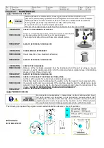
Page 38: ...rom the internal plate of the cart by using a vacuum cleaner or specific cleaning products After the cleaning of plate spread a layer of lubricating grease on the surface using a brush FREQUENCY ALWAYS BEFORE EACH SINGLE USE OPERATION CHECK OF THE SAFETY DEVICES FUNCTIONALITIES PROCEDURE Let the machine works for some minutes and simulates a test Check the safety devices functionalities the switch...

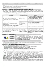
Page 39: ...nnect the air supply and remove the rear cover of the machine Through the connection of supply air of the pneumatic cylinder placed in the top flange insert grease Chapter 10 SPARE PARTS WARNING DANGER Only original spare parts can be used Use of unoriginal spare parts exempts the manufacturer from all responsibility Procedures for substitution of spare parts will be provided by the manufacturer a...

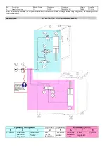
Page 40: ...or deplete devices that will come back through these recycling sites according to the local statement ENCLOSURE I PNEUMATIC SYSTEM DIAGRAMS Gyratory Compactor optional optional Extruder optional 1 2 3 4 5 6 7 8 Cylinder Pneumatic Precision Regulator Automatic Valve FR FILTER REGULATOR Pressure source manually actuated valve Flow regulator Cylinder ...

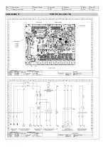
Page 41: ...Rev Descrizione Redatto Gestito Approvato Cod Ident Pagine Data Em 0 6 Manuale Istruzioni GN UTEC B041 M01 EN 41 47 07 2014 ENCLOSURE II WIRING DIAGRAMS ...

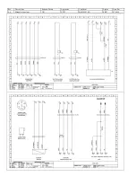
Page 42: ...Rev Descrizione Redatto Gestito Approvato Cod Ident Pagine Data Em 0 6 Manuale Istruzioni GN UTEC B041 M01 EN 42 47 07 2014 ...

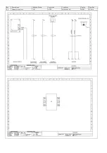
Page 43: ...Rev Descrizione Redatto Gestito Approvato Cod Ident Pagine Data Em 0 6 Manuale Istruzioni GN UTEC B041 M01 EN 43 47 07 2014 ...

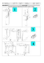
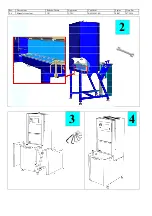
Page 44: ...ione Redatto Gestito Approvato Cod Ident Pagine Data Em 0 6 Manuale Istruzioni GN UTEC B041 M01 EN 44 47 07 2014 ENCLOSURE III ACCESSORY Assembling Integrated worktop Mechanical automatic specimen extruder 1 2 3 4 ...

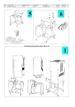
Page 45: ...Rev Descrizione Redatto Gestito Approvato Cod Ident Pagine Data Em 0 6 Manuale Istruzioni GN UTEC B041 M01 EN 45 47 07 2014 5 6 Assembling Integrated worktop Machine 1 ...

Page 46: ...Rev Descrizione Redatto Gestito Approvato Cod Ident Pagine Data Em 0 6 Manuale Istruzioni GN UTEC B041 M01 EN 46 47 07 2014 3 4 2 ...

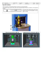
Page 47: ...the testing chamber and put it on the extruding piston Check that the lower collar of the mould is well contained between the three contrast pins of the specimen extruder DANGER Do not touch the mould and any part of the extruder during the extruding phase to avoid fingers crushing Vertical force testing device B041 30 Digital vertical force testing device B041 31 ...

Reviews: