background image

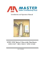
MWC-EM Solenoid and 304 Electro Polished SS Vessel 

Installation: 


1.

  The ultraviolet unit is designed to be installed in a vertical position.  

The unit is supplied with (2) brackets to support the unit.   

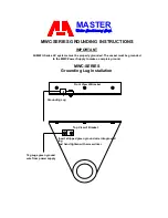
NOTE: The upper bracket has a grounding lug attached to it 

2.

  Place the top bracket (larger one) over the nipple located at the 

top of the vessel.  The end of the bracket with the three holes 

should be facing up towards the top of the vessel. 

3.

  Tighten the gray PVC ring onto the nipple.  This will compress 

down onto the top of bracket. 

4.

  Attach the smaller bracket to the bottom of the vessel.  The 

bracket has a clip type fastener that attaches to the bottom rim of 

the vessel.  The end of the bracket with the three holes should be 

facing down towards the bottom of the vessel. 

5.

  Secure the top bracket to a wall by using three appropriate screws 

or fasteners (not provided).  

Be sure to leave plenty of clearance above vessel for servicing 

the quartz tube and germicidal lamp. (For proper clearance, see 

Specification Table on page 2) 

6.

  Secure the bottom bracket to the wall by using three screws or 

fasteners (not provided). 

7.

  Use quality unions and ball valves on the inlet and outlet for 

servicing the unit.  

See Page 2

 for a typical installation piping 

layout.  If sweat fittings are used, be sure soldering is done in such 

a manner as not to allow heat to reach the UV vessel.  If Schedule 

80 PVC or CPVC is used, make sure to follow the proper primer 

and solvent instructions. 

8.

  Pipe the 

inlet

 into the 

bottom

 nipple of the UV vessel.


9.

  Install a 1’’ x 3/4” reducing bushing (not provided) into the inlet of 

the solenoid valve.


10.

  Install the ¾” (for the EM7 and EM10 units) or the 1” (for the 

EM20 units) normally closed solenoid to the 

outlet 

on the 

top  

nipple of the UV vessel. Make sure that the solenoid is installed in 

the proper direction.  

See page 2

 There is an internal flow 

restrictor in the outlet nipple of all units.  

It is recommended you 

install a boiler drain on the inlet piping of the unit.  This will 

allow for easy draining of the vessel when replacing the UV 

quartz.


Summary of Contents for MWC-EM Series

Page 1: ...MWC EM Series Ultraviolet Sterilizers MWC EM7 MWC EM10 MWC EM20 Installation and Operation Manual 2022 VERSION...

Page 2: ...ts MWC Meter Power Supply Meter Power Supply Installation 7 Grounding Grounding Instructions 8 Quartz and O ring Installing Quartz and O ring Germicidal Lamp Installing Germicidal Lamp MWC EM Meter St...

Page 3: ...of our MWC EM Water Sterilizers Shipping Description The UV unit is shipped complete as follows The large box contains the UV vessel and inside that box you will also find the following 1 A box conta...

Page 4: ...the maximum allowable levels specified this will result in bacteria passing through the UV unit and into the piping system Unit Location 1 The MWC EM unit must be installed after the well tank and any...

Page 5: ...ng the quartz tube and germicidal lamp For proper clearance see Specification Table on page 2 6 Secure the bottom bracket to the wall by using three screws or fasteners not provided 7 Use quality unio...

Page 6: ...ring this is on the quartz eyepiece 4 Insert the UV sensor assembly with gray gland nut Hand tighten only 5 Attach the other end of the UV sensors black amp electrical connection to the lower right s...

Page 7: ...power 24 hours per day We recommend installing a surge protector to protect unit from power surges which are not covered by warranty DO NOT UNDER ANY CIRCUMSTANCE WIRE THE UV UNIT TO THE WELL PUMP SW...

Page 8: ...rly grounded The vessel must be grounded to the MWC Power Supply to make a complete ground MWC SERIES Grounding Lug Installation Grounding Lug Front View of Bracket Insert stripped green ground wire i...

Page 9: ...3 Gently insert the germicidal lamp into the quartz sleeve through the center of the clear gland nut located at the top of the vessel Be careful not to drop the lamp inside the vessel This could break...

Page 10: ...ses interference in the UV vessel 1 Shut off the water to the inlet and outlet of the cartridge filter 2 Remove the cartridge sump and empty all water Fill with household chlorine Clorox non scented 5...

Page 11: ...tlet with power 24 hours per day 3 Check all piping for leaks repair if necessary 4 Unplug the 1 normally closed solenoid from the electrical outlet and plug the solenoid into the lower right side of...

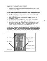
Page 12: ...driver Remove the black cap located on the upper right side of the meter 5 With the unit on and operating turn the lower screw clock wise turn at time until you reach 100 The MWC EM unit is now workin...

Page 13: ...y pulling up on the gray harness wire and discard the lamp Remember the lamp is glass and can cause injury to you if the lamp is dropped 5 Open the ball valve test port on outlet side of UV unit to de...

Page 14: ...port and plunger Defective solenoid replace Symptom Alarm is on and no flow of water and Meter is reading less than 50 and Lamp is on and Gland Nut is glowing blue Cause Solution Lamp is over a year o...

Page 15: ...where the ultraviolet sterilizer has been operated at pressure in excess of 100 pounds per square inch or at a temperature in excess of 100 degrees F or below 32 degrees F Incidental costs or conseque...

Page 16: ...driver Remove the black cap located on the upper right side of the meter 5 With the unit on and operating turn the lower screw clock wise turn at time until you reach 100 The MWC EM unit is now workin...

Page 17: ...nnection to the lower right side of the meter Insert the amp into the twist lock connector The connector will only fit into the connector one way Hand Tighten Only UV Sensor Assembly Quartz Dome Eyepi...

Page 18: ...nt is required before installation of the UV unit Water must meet criteria below Untreated Water Quality Maximum Allowable Level Chloride 250 00 ppm Color 0 00 units Hardness 8 00 gpg Iron 0 30 ppm Ma...

Page 19: ...ore consumption of water an EPA Lab Test is suggested MWC EM SERIES TROUBLESHOOTING Symptom No flow of water no Alarm and Gland Nut not glowing Cause Solution Electric Supply Check electrical outlet a...

Reviews: