background image

57

58

          
Tips

Note 1: If ‘READ’ button is pushed instead of ‘ENTER’ button, data will not be deleted and the system will directly return to the 
             previous interface.

5.3 Deleting data

Operation procedures

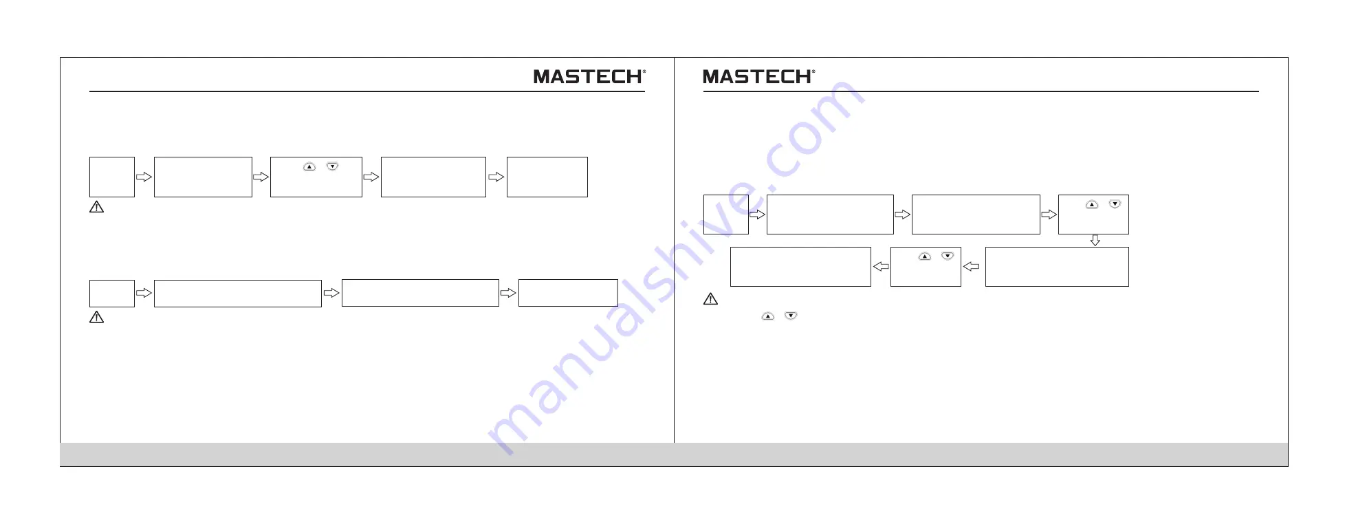
5.3.1 Delete specified data

Push ‘READ’ button 
to display ‘READ’ 
symbol.

Push ‘ENTER’ 
to delete the 
selected data. 

Push ‘CLEAR’ button, 
and ‘Clr’ symbol is 
displayed.

Standby 
status

Push ‘      ’,‘      ’ to 
select the data No. 
for deleting. 

          
Tips

Note 1: If ‘READ’ button is pushed instead of ‘ENTER’ button, data will not be deleted and the system will directly return to the 
             previous interface.

Delete all manually-saved records and log-records. 
Procedures

5.3.2 Deleting all data

Push ‘READ’ button, and ‘READ’ 
symbol will be displayed on screen. 

Push ENTER button 
to delete all data.

Push ‘CLEAR’ button twice, and 
‘ALL Clr’ symbol will be displayed

Standby 
status

6. Other Functions

          
Tips

6.1 Changing and checking the time interval for calculating PI 

Operation procedures

6.1.1 Changing the settings for time intervals 

Push ‘SELECT’ button 
for multiple times until 
PI is displayed on screen.

Push ‘Enter’ button to confirm 
the first time interval and ‘t2’ 
symbol will be lit up.

Push ‘TIMER’, and the first 
time interval will flash and 
‘t1’ symbol will be lit up.

Standby 
status

Use ‘      ’,‘      ’ 
to set time. 

User can define and set the two time intervals that are needed for displaying PI value. 
You can choose from 1 minute to 30 minutes, while the default settings are: t1 = 1 min, t2 = 10 min. 

Push ‘Enter’ button to confirm 
the second time interval and 
return to PI display. 

Use ‘      ’,‘      ’ 
to set time. 

Note 1: Use ‘      ’,‘      ’ button to set the time, where the second time interval must be greater than the first one. 
Note 2: If the time interval is not the default value, then 10 / 1 min will not be displayed during PI displaying; Under this 
             situation, the measured insulation resistance value is used to calculate PI at the set time intervals. 
Note 3: After the time intervals are changed, the measured PI values cannot be changed. 
Note 4: If ‘CLOCK’ button is pushed during parameter-setting, the set parameters will not be changed and the system will  
             return to the standby mode. 
Note 5: Time intervals can also be set via the communication software that is installed on a PC. 

Summary of Contents for MS5215

Page 1: ...High Voltage Insulation Tester MS5215 User s Manual ...

Page 2: ...cedures 2 5 Connecting the temperature sensor 2 5 1 Operation procedures 3 Test Methods 3 1 Checking before the Test 3 1 1 Checking procedures 3 2 Insulation resistance test 3 2 1 Start testing 3 2 2 Finishing a test 3 2 3 Review and delete the held data 3 2 4 Auto discharging function 3 2 5 Reviewing other test data 3 2 6 Principle of insulation resistance test 3 2 7 Using GUARD terminal 3 3 Volt...

Page 3: ... Attached Table 03 04 Contents 4 2 Displaying PI and DAR 4 2 1 Application of PI DAR 4 2 2 Operation procedures 4 3 Temperature Compensation 4 3 1 Application 4 3 2 Applying temperature compensation 4 3 3 Exiting the mode of temperature compensation 4 4 Step Voltage Measurement 4 4 1 Setting and managing step voltage test 4 4 2 Reviewing test data at every step 4 4 3 Exiting the mode of step volta...

Page 4: ...e accessories the control switches and the connection devices should be checked Please contact your supplier in case there is any obvious damage or any malfunction Procedures 1 Use your fingers to pull the lock buckle outward 2 Lift the lock buckle upward so as to release the two buckles and open the out case Lock buckle Lock buckle Handle ...

Page 5: ...njury might occur Our company is not liable for any accident involving physical injury that is caused by reasons other than flaws of the testing instrument itself Safety Symbol Descriptions This manual contains basic points of operation safety and tester maintenance Please read the following safety information carefully before use Table 1 Safety Information Caution risk of danger Equipment protect...

Page 6: ...guaranteed 101 MΩ 20 GΩ 21 GΩ 500 GΩ 501 GΩ 5 TΩ 85 RH no condensation 75 RH no condensation 65 RH no condensation 55 RH no condensation 23 ºC 5 ºC 73 ºF 9 ºF Please observe the following instructions to avoid electrical shocking and short circuiting Before connecting or disconnecting a tester probe please make sure that the probe is detached from the object being measured and the power is turned ...

Page 7: ...nt temperature changes abruptly in great number of degrees it might result in condensation which will cause incorrect measurements Before starting the measurement please first place the meter under the new test environment for a period of time Tips Common unit conversion for electrical measurements 1 TΩ Tera ohm 1000 GΩ 10 Ω 1 GΩ Giga ohm 1000 MΩ 10 Ω 1 MΩ Mega ohm 1000 KΩ 10 Ω 1 mA milli ampere 0...

Page 8: ...y an alkaline battery 2 This tester can be continuously operated for a longer period of time than similar meters if a LR14 alkaline battery is used Powered by Batteries 1 3 General Description of Test Methods 1 Use for checking the insulation of high voltage electrical equipment 2 Situation high voltage receiving station and transformer substation 3 Object electric motor transformer and cable etc ...

Page 9: ...hart Connect test probes to terminals and the test equipment as shown in Fig 1 4 Read data as shown in Fig 1 5 1 3 2 3 1 Voltage test Red line Black line Fig 1 1 Fig 1 2 Fig 1 3 2 Red Line Black Line Fig 1 4 Fig 1 5 ...

Page 10: ...ER button to end test as shown in Fig 1 8 Temp Fig 1 6 Fig 1 7 Fig 1 8 1 3 2 3 2 Data holding 1 4 Names and Functions of Components 1 USB socket For connecting a USB cable 2 Temperature sensor socket For connecting a temperature sensor 3 Socket cover For preventing connection to another socket when connecting a test probe 4 L terminal For connecting the red meter probe 5 GUARD terminal For connect...

Page 11: ...he reading for insulation resistance AVG Displaying average value TEMP HOLD Holding temperature value MONTH Month TIMER Timer DAY Day h Hour min Minute s Second USED With data saved TABLE NO Temperature compensation ºC ref Reference temperature ºC Degree Celsius RH Humidity TC Temperature Compensation READ No Read No MEMO No Memo No Battery selection switch Alkaline battery ...

Page 12: ...ltage 2 For toggling between the set voltage and the testing voltage after a resistance test is completed 3 It will flash after the testing voltage is generated 4 It will flash if the input voltage is greater than 50 V or when discharging occurs Buttons 1 SELECT 1 For changing the displayed item 2 For toggling between resistance and current display during a resistance test 3 For switching the disp...

Page 13: ...wer and take off all the test probes 2 Loose the screws on the back and take off the battery cover 3 Place 6 X LR14 alkaline batteries in the battery case 4 Switch the battery selection switch to alkaline battery 5 Put back the battery cover and tighten the screws 1 Press and hold POWER button for more than 2 seconds and the screen display will be turned on and the tester will be under standby mod...

Page 14: ...e change and return to standby mode Gently touch button to change flashing data Gently touch CLOCK button and hold it for more than 1s and the display will flash and data can be changed 2 3 2 1 Operation procedures 2 3 2 Checking date and time Standby status Gently touch CLOCK and year month day will be displayed Gently touch CLOCK and hr min sec will be displayed 2 4 1 Operation procedures Check ...

Page 15: ...esting voltage and resistance 5 Prepare a calibration resistor voltage proof value 5 kV resistance 20 MΩ also prepare a DC voltage meter input resistance greater than 1 000 MΩ measuring range for voltage greater than 5 5 kV DC Check the readings on the voltmeter and the tester between 5 and 5 5 kV Gently touch MEASURE button to stop insulation measurement Check if the reading of insulation resista...

Page 16: ...ther reasons such as battery leakage under this situation auto discharging function might be invalid and therefore please use a discharging rod to discharge the test object 1 In order to avoid damaging the equipment that is to be tested please check the test voltage before measurement 2 For repeating a test please press button prior to the next measurement and check the test voltage 3 In order to ...

Page 17: ...ues will be displayed on screen 1 Insulation resistance with the value and a graduation bar 2 Testing voltage 3 Actual output voltage 4 Leak current 5 Time spent for the measurement Press the buttons shown in the following table to switch the display for other measured data Gently touch measure button to hold the last measured data and HOLD symbol will be displayed The tester will do auto discharg...

Page 18: ...ue and leak current value This is caused by polarization effect which occurs when applying voltage on the insulation material Insulation material can be represented by an equivalent circuit as shown in the diagram below IA stands for the absorbing current generated by slow polarization it takes some time for the polarization resulted from last test to disappear There is still charge remaining in C...

Page 19: ...dile clip 5 In case the cover of the socket is damaged please do not use the tester Rc insulation resistance of the insulation material for high voltage cables between core and metal shielding layer Rs insulation resistance of the protective layer for high voltage cables between metal shielding layer and earth Rn insulation resistance between the insulation device or high voltage equipment and ear...

Page 20: ... damage the temp sensor Do not bend the sensor cable 4 Advanced test functions 4 1 Use of the timer 4 1 1 Setting the timer controlling insulation resistance test Application 1 It can be used to automatically stop the test after a preset period of time 2 With the timer function time can be set between 30 seconds and 30 minutes When the set time is greater than 1 minute it can be adjusted in steps ...

Page 21: ...or polarization index can give you information about the degree to which the insulation devices of generator and oil dip power transformer are subject to dampness After insulation parts are subject to dampness the absorption ratio or polarization index decreases as shown in Fig 1 and therefore it is an important index for telling out whether an insulation part is subject to dampness 2 PI and DAR v...

Page 22: ... button to stop test Push MEASURE button to start test Push SELECT button to check PI DAR data Tips Note 1 In order to display DAR value AVERAGE function must be turned off before measuring Note 2 In order to display PI value the time spent for measuring insulation resistance must be longer than 10 minutes under the default situation Note 3 In order to display DAR value the measuring time must be ...

Page 23: ... however the displayed leak current will be the value without compensation Operation procedures Temperature reference temperature time spent Actual temperature setup idle mode 4 3 3 Application Push button to select compensation table Push TC button and TABLE No symbol will flash Push button to adjust the reference temp value Push Enter button to confirm it and TC symbol will be displayed Push MEA...

Page 24: ...ltage test Use button to adjust the test voltage to 5 kV Test voltage increases in preset steps and afterwards the test will be automatically stopped Push button and the set test voltage will flash Push Enter button to switch to mode of step voltage test and Step symbol will be displayed 4 4 2 Reviewing test data at every step Standby status Push CLOCK TIMER button to toggle between resistance and...

Page 25: ...voltage actual output voltage last measured resistance value measured resistance value after 15 seconds measured resistance value after 30 seconds measured resistance value after 1 minute user defined PI time interval resistance value at user defined time interval Data saved in each record Type of data Standard test data Mode of Recording Manual recording Data number year month day hour minute sec...

Page 26: ...d Note 5 If power is turned off when MEMO No symbol is flashing data will be lost 5 1 2 Log recording 1 The tester saves values of insulation resistance at the specified intervals and altogether 10 groups of data can be saved Lr0 Lr9 with each group containing up to 360 values The time interval can be chosen from 15 seconds 30 seconds 1 minute 2 minutes and 5 minutes 2 The number of data that can ...

Page 27: ... measure button is pushed Data number starts flashing at the end of measurement while data has not been saved at this moment 3 Temperature measurement can be carried out when necessary which can be skipped usually Temperature and humidity values that are measured with an external thermometer and hygrometer can also be entered into the tester Tips Note 1 If the measurement stops before the first ti...

Page 28: ... 3 If STEP is displayed then it is step voltage measurement data 5 2 3 1 Reviewing standard test data Use to select the data No for reviewing 5 2 2 Mode of displaying for recorded data The recorded data can be categorized into standard test data temperature compensation data and step voltage measurement data A lot of data are not directly displayed on screen and therefore you need to push SELECT b...

Page 29: ... 5 2 3 3 1 Mode of typical data display Displayed values for switching Button used Time spent temperature humidity TEMP Date of test time of test data MEMO Return to standby mode READ The set voltage actual output voltage Accessing the mode of detailed data display SELECT Displayed data The test data in the last step Test data in every step Push SELECT button under the mode of typical data display...

Page 30: ...CT button for multiple times until PI is displayed on screen Push Enter button to confirm the first time interval and t2 symbol will be lit up Push TIMER and the first time interval will flash and t1 symbol will be lit up Standby status Use to set time User can define and set the two time intervals that are needed for displaying PI value You can choose from 1 minute to 30 minutes while the default...

Page 31: ...age application time in each step rather than the total time in all the five steps 1 Push button under the mode of standby and the voltage indication starts flashing 2 Select a mode of step voltage measurement STEP 2 50 kV SET or STEP 5 00 kV SET and push ENTER button and then the time for every step will be displayed 6 2 2 Checking the settings for time 6 3 Entering temperature humidity values me...

Page 32: ... 100 MB remaining space Interface USB 6 Functions of the PC software 1 Obtain the saved data from the tester 2 Display the obtained data and log record and make curves for the step voltage measurement and save test data 3 Set tester parameters 7 Parameters that can be set on a PC 1 Date and time 2 Time interval for calculating PI 3 The applied time for step voltage test Tips Note 1 When TC symbol ...

Page 33: ...XE 2 Click NEXT 6 4 1 Installing the PC software 3 Select I accept the above terms and conditions and click NEXT Welcome to install Insulation Resistance Tester V1 0 wizard Press next to continue Back Next Cancel License agreement Please read the following license agreement carefully I agree the terms I do not accept Back Cancel Next ...

Page 34: ...installation directory and click NEXT 5 Click NEXT Program ready to install Cancel Next Back Confirm Installation Press next to continue Destination folder Select Destination folder then press next Back Next Cancel Browse ...

Page 35: ...alling 7 Click Finish to complete the installation Back Cancel Next Duringthe installlation please wait Decompressing files Insulation Rsistance Teter V1 0 Please press finish to exit the installation Cancel Finish Back ...

Page 36: ...r and it will display new hardware found on screen If a wizard dialogue box for auto updating Windows pops up select NO and click on Next Step button once This dialogue box does not pop up in certain versions of Windows XP instead the dialogue box that is described in the forth step pops up 4 Choose install from list or install from specified folder advanced and click NEXT STEP once Insulation Res...

Page 37: ... and then select the file USB_DRIVER from the CD and then click NEXT 6 Auto searching Select Search and Install Option Auto Searching Driver from specified folder Search CD and Floppy Search Specified Folder Search Driver by Manual Back Cancel Next Searching Back Cancel Next ...

Page 38: ...plug to the USB socket on the meter 3 Run the communication software on PC Table 1 Ambient temp and humidity for test 0 40 C 85 RH without condensation Temperature for battery charging 10 40 C 80 RH Storage temperature and humidity 10 50 C 90 RH without condensation Temperature and humidity for battery pack storage 20 30 C 80 RH without condensation Operation environment For elevation lower than 2...

Page 39: ...harging Max powering time Alkaline battery about 9 hours Battery pack about 5 hours with 5 kV voltage generated with terminals in an open circuit and with backlight turned off Table 3 Standard accessories 1 Test cable 3 m 3 2 Crocodile clips 3 3 Instruction manual 1 4 LR14 alkaline battery 6 5 USB cable 1 6 Temperature sensor 1 7 CD 1 Optional accessories 1 Rechargeable battery pack 2 AC charger T...

Page 40: ...ion Auto powering off SYSTEM RESET function Data that can be tested insulation resistance leak current voltage and temperature 7 2 1 Insulation resistance test Test range Threshold value of basic error 250 V DC 0 01 MΩ 2 5 GΩ 5 rdg 5 dgt 2 51 GΩ 250 GΩ 20 rdg 10 dgt 500 V DC 0 01 MΩ 5 0 GΩ 5 rdg 5 dgt 5 01 GΩ 500 GΩ 20 rdg 10 dgt 1000 V DC 0 01 MΩ 10 GΩ 5 rdg 5 dgt 10 1 GΩ 500 GΩ 20 rdg 10 dgt 501...

Page 41: ...t with AVERAGE function turned off Range of insulation resistance Range of humidity within which insulation resistance test precision is guaranteed Range of temperature within which insulation resistance test precision is guaranteed 85 RH no condensation 23 ºC 5 ºC 73 ºF 9 ºF 75 RH no condensation 65 RH no condensation 55 RH no condensation 10 nA 100 nA 1000 nA 10 μA 9 0 μA 99 9 μA 90 μA 999 μA 0 ...

Page 42: ...s cannot be charged Insulation In case the tester does not function well please first conduct checks according to the below table Check polarity Are batteries charged Charge the rechargeable battery Is the charger correctly attached 2 1 3 Check if the charger is correctly attached Are rechargeable batteries installed 2 1 2 Install rechargeable batteries Is there a problem with test probes Replace ...

Page 43: ...argeable batteries 2 Take off the four screws on the back and take off the bottom cover 3 Take off the screws for fixing the two circuit boards and take out the circuit board Do not take off the circuit board that is closer to LCD 4 The lithium battery is on the remaining circuit board Insert tweezers or other similar tools in between the battery and the battery holder and then take off the batter...

Page 44: ...fficients of power cables see the coefficients listed in the below table Rtref At Atref Rt Atref reference temperature coefficient At the actual temperature coefficient for real measurement Rtref resistance after temperature compensation Rt resistance under t temperature Tref reference temperature T the actual temperature during measurement Temperature C Oil dipped insulation cable poly vinyl fluo...

Page 45: ...2 79 27 2 05 1 44 1 87 1 45 2 40 1 54 2 08 1 55 1 76 3 22 28 2 70 1 65 2 31 1 65 0 48 0 52 0 58 0 59 0 63 0 74 0 71 0 74 0 79 0 82 0 85 0 58 0 62 0 66 0 7 0 75 0 64 0 68 0 72 0 76 0 81 1 92 3 71 29 3 80 1 77 2 57 1 77 Temperature C Oil dipped insulation cable poly vinyl fluoride insulation cable Normal rubber Normal SBR rubber Butyl rubber Coefficient A Table 3 1 3 KV 6 KV Table 4 Table 5 Table 6 ...

Page 46: ...temperatures 20 60 C Range of convertible actual temperatures under which tests are performed 20 60 C Compensation equation Rtref 10 5 Rt Rtref resistance after compensation Rt resistance under t temperature Tref reference temperature T the actual temperature during measurement 00 05 4222 ...

Reviews: