MASSOTH
DiMAX
®
1203B Digital Booster
Digital Booster 3 x 4 Amps for NMRA compatible model railroads
Item No.: 8141001
Version 1.00 – 12/07
Page 1: ...MASSOTH DiMAX 1203B Digital Booster Digital Booster 3 x 4 Amps for NMRA compatible model railroads Item No 8141001 Version 1 00 12 07 DiMAX 1203B Digital Booster ...
Page 2: ...ing the Modes of Operation 11 4 2 Overvoltage Protection 11 4 3 Overload Protection 11 4 4 Loss of Signal from the Central Station 11 4 5 Adjustment of the Output Voltage 11 5 Operational Mode 1 Booster 12 5 1 Connecting the Outputs in Parallel 13 5 2 Operational Mode 2 Booster with Reverse Loop Function 14 5 3 Operational Mode 3 Booster with Braking Function 15 5 4 Special Function with Slow Spee...
Page 3: ...230VA Voltage limitation track voltage is limited to 23 5 V if powered by DC supply Adjustible output voltage from 14V to 22 V if powered by AC supply Integrated fan temperature controlled 3 stage LED status indication per channel NMRA DCC compatible LGB MZS compatible Booster interface Lenz CDE interface Central Navigator interface see note page 2 III Layout of Terminals External power supply 12V...
Page 4: ...tic compatible cleaner or dry soft cloth only 1 1 8 We stress the fact that this product is not a toy Do never leave your children unattended when opera ting the DiMAX 1203B Digital Booster Children should operate this item only under supervision of adults 1 1 9 Never use analog transformers on the same track with digital components This goes for the operation of catenary lines also 1 1 10 Keep th...
Page 5: ... firmware update go to www massoth com Further support is available through your retailer or via the Massoth USA Hotline Hotline hours USA 9 00 a m to 4 00 p m EST Monday thru Friday Massoth Electronics USA LLC 6585 Remington Dr Cumming GA 30040 Ph 770 886 6670 Fax 770 889 6837 2 Scope of Supply DiMAX 1203B Digital Booster Multi Connector for power hook up 3 x Track power connector 1 x Lenz CDE co...
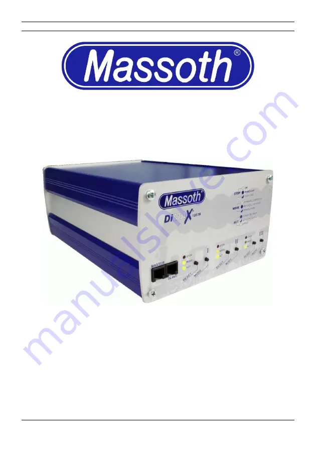
Page 6: ... 1203B Digital Booster should not be placed close to a radiator any heating device or in direct sunlight At all times ensure sufficient ventilation and a proper temperature range for the DiMAX 1203B Digital Booster The ventilation outlet is on the rear panel and it should be kept clear of any obstructions at all times 5 DiMAX 1203B Digital Booster Illustration 1 The front panel of the DiMAX 1203B ...
Page 7: ...MASSOTH 3 2 Power Supply DiMAX 1203B Digital Booster 6 Illustration 3 Power Terminal Illustration 2 The rear panel of the DiMAX 1203B Digital Booster ...
Page 8: ...y The power supply input is fused with a separate fuse on the rear panel of the DiMAX 1203B Digital Booster see illustration 2 A 10 Amp slow blow fuse must be used 3 4 Track Hook Up The DiMAX 1203B Digital Booster features 3 power outputs which may be connected in par allel For the first test operation connect output 1 to the track Parallel operation is explained later in Chapter 5 1 Connect your ...
Page 9: ...l Navigator see note page 2 only The Slave terminal may be used as a regular control bus terminal for DiMAX components These terminals may only be used for the operation of a Central Navigator see note page 2 in conjunction with DiMAX components A regular Navigator does not work when connected to this jack 3 6 Hook Up with a DiMAX LGB oder Lenz central station or compatible The rear panel Illustr ...
Page 10: ...or the correct wiring The DiMAX 1203 Booster connects to a DiMAX or LGB central station MTS II or III via the 4 pole booster bus terminal Utilize the booster interface cable to hook up the booster to the central station 9 DiMAX 1203B Digital Booster ...
Page 11: ...s of the operation and the actual status of the layout There are three LED indicators provided per channel Illustration 6 shows all the variations of indica tions possible The respective modes are explained in chapter 5 DiMAX 1203B Digital Booster 10 Illustration 6 LED Status Indications ...
Page 12: ...op LEDs are illuminated In this case the supply voltage is too high and the booster switches off for safety reasons Make sure to operate the DiMAX 1203 Booster within the specifications Disconnect the DiMAX 1203 Booster briefly from the power source to reset the system 4 3 Overload Protection In case one or more channels are showing a flashing red LED the respective channel has been switched off d...
Page 13: ...atible central station is shown in chapter 6 1 In case two or three outputs are used in the same layout connect the outputs according to il lustration 8 Make sure the outputs are connected to the track in the same polarity al ways connect output to track and output to track DiMAX 1203B Digital Booster 12 Illustration 7 Wiring diagram in mode 1 with 1 output Illustration 8 Wiring Diagram Mode 1 uti...
Page 14: ...nti nuously Important The channels need to be connected in the same polarity Otherwise com ponents connected to the DiMAX 1203B might be damaged or destroyed as well as the booster itself The wiring diagram is shown in illustration 9 The section points may be crossed without hesitation operating DiMAX or MZS II resp III central stations in connection with the DiMAX 1203B booster 13 DiMAX 1203B Dig...
Page 15: ...B Booster is operating as a reversing loop module Illustration 10 shows a typical wiring diagram In this setup channel 1 is working in mode 2 reversing loop and channel 2 is working in mode 1 booster DiMAX 1203B Digital Booster 14 Illustration 10 Wiring diagram with mode 2 reversing loop ...
Page 16: ...is working in mode 3 brake and stop functi on In case the signal shows GO the first and second block is supplied with power by channel 3 the train will pass through In case the signal shows STOP the relay switches over when the train passes the track con tact Block 1 will be powered by channel 3 and block 2 will be powered by channel 2 The train will stop after it passed the track contact If the s...
Page 17: ... speed of the train is set by pressing the mode button of channel 2 repeatedly The speed changes in 14 steps to 0 and starts again with 14 The LED of channel 2 will flash according to the speed setting fast for high speed slow for slower speeds The set up in illustration 13 works as follows In case the warning signal advance signal is not set and the following signal shows GO the train will pass t...
Page 18: ...tions track construction sites or secti ons with steep down grades You may find detailed examples on our home page http www massoth com 6 Operation with the Central Navigator see note page 2 You may connect a Central Navigator to the DiMAX 1203 Booster Important In this case the booster and CDE interface must not be used Connect the Central Navigator see note page 2 to the Master plug you may conn...
Page 19: ...Interface Depending on the type of central station it must be tested whether a passage from the boos ter powered section to the section powered by the central station is possible In case one of the components is producing a short circuit the time base of the two components is different and a passage from the booster section to the central station section is not possible DiMAX 1203B Digital Booster...
Page 20: ...e that the track power connector of the central station must never be connected to one of the outputs of the DiMAX Make sure that there is no connection of the booster powered track section to a track section that is powered by the central station 19 DiMAX 1203B Digital Booster Illustration 14 Wiring Diagram in Mode 1 with Central Stations of other manufacturers ...
Page 21: ...sting of eight bits The decimal value of a byte varies between 0 and 255 Central Station The central station is the brain of a digital system All commands feedback instructions etc are processed in the central station The central station generates the bi polar DC waveform which is subsequently amplified by a DCC booster to power the track bus The central station communicates with DCC components ca...
Page 22: ...perate a switch control a motor control lighting outputs Locomotive decoders receive power and instructions from the bi polar DCC waveform transmitted along the rails Digital System A digital system is an electronic control system designed to allow independent operation of multiple trains on the same track Commands sent to mobile decoders allow the user to control motor speed and direction as well...
Page 23: ...ypically the locomotive address CVs cannot be changed with PoM Please note some decoders are not compatible with PoM Massoth eMOTION XL XLS decoders are compatible with PoM LGB 55020 55021 55022 55027 and LGB onboard decoders are not compatible with PoM Protocol Protocol is a set of conventions governing the formatting of data in an electronic communications system In essence the system protocol i...
Page 24: ...open fire 9 Manufacturer Information Massoth Elektronik GmbH Frankensteiner Str 28 64342 Seeheim Malchen Germany PH 011 49 6151 350770 FX 011 49 6151 3507744 Massoth Electronics USA LLC 6585 Remington Dr STE 200 Cumming GA 30040 Ph 770 886 6670 FX 770 889 6837 V1 0 12 07 ST Massoth and DiMAX are registered trademarks by Massoth Elektronik GmbH Seeheim Germany LGB is a registered trademark and prop...