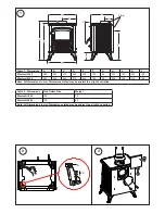
Floor Protection & Installation Clearances
Please refer to the speci
fi
c ‘Installation Speci
fi
cations’ for the stove
concerned supplied with the stove.
Flue Connection
You MUST use a
fl
ue system, which complies with the current
installation Standard AS/NZS 2918.
Full instructions are supplied with the
fl
ue kit, and these MUST be
followed closely, including the minimum
fl
ue exit height from the
top of the
fl
oor protector and the minimum exit height above the
roo
fl
ine or roof ridge as detailed in the instructions.
Other Flue Systems
Flues and
fl
ue heat shields other than those listed on the Installation
Speci
fi
cation Sheets may be used, but if they have not been tested
with these heaters, their installation clearances will be those
speci
fi
ed in AS/NZS 2918:2001 for untested
fl
ue installations.
Unless otherwise speci
fi
ed, all heat sensitive wall material must
be kept at least 600mm away from any
fl
ue, which is not
fi
tted
with a
fl
ue heat shield.
Always seal the
fl
ue to the
fl
ue socket of the
fi
rebox using
fi
rebox
cement or
fi
berglass rope.
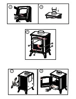
Connect the
fl
ue pipe to the stove making sure that it
fi
ts snugly
into the base of the
fl
ue collar
(Fig.5)
. Seal the collar and
fl
ue
connection with
fi
re cement or with other suitable high temperature
sealant. Add
fl
ue sections as required; note that all
fl
ue sockets
must face upwards.
Avoid using bends greater than 45° to the vertical. All
fl
ue pipes
should be as close to vertical where possible. For rear flue
connection the length of the horizontal run of the
fl
ue pipe should
not exceed 150mm.
This product should not be installed on a shared fl ue.
Commissioning
Upon completion of installation, the stove and
fl
ue system should
be tested by a suitably quali
fi
ed person to make sure it is safe for
normal use. A smoke draw test should be completed to check for
soundness of joints and seals and also that all smoke and fumes
are taken from the appliance up the chimney and emitted safely.
First warm the
fl
ue with a blowlamp or similar for about 10 minutes.
Place a lit smoke pellet on the centre of the grate with the air
controls open. Close the door – the smoke should be drawn up the
fl
ue and be seen to exit from the
fl
ue terminal. Complete the test
with all windows and doors shut in the room where the appliance
is
fi
tted. If a ceiling fan is present it must be operated on max for
the duration of the test. If there are any extraction fans in adjacent
rooms these too must be operated on maximum setting during the
test with the interconnecting doors open. If any spillage occurs,
recheck the suitability of the
fl
ue system making sure there is
adequate air supply to the room (as per Building Regulations).
Light the appliance and slowly increase the temperature to
operating levels. Open the main
fi
re door when the appliance
reaches normal operating condition and carry out a spillage test
using a smoke match or pellet around the door opening. If any
spillage occurs, open all windows, allow the
fi
re to go out and
recheck the
fl
ue system and ventilation.
- 4 -
Operating Instructions
Warning: The door and operating handles become hot when
the stove is in use. For your safety use the glove provided.
Initial Firing of Stove
We recommend that you have two to three small
fi
res before you
operate your stove to maximum heat output. This is to allow the
paint to cure and the castings to relax and consolidate location.
We recommend this ‘running in’ procedure after long idle periods
to preserve the life of the stove. During this you may notice an
unpleasant smell. It is not toxic but for your own sake we would
suggest that during this period you leave all doors and windows
open.
Air Controls
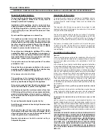
Primary air is controlled via the sliding vents
(A - Fig 6)
in the
bottom of the door; this provides a conventional air draught to the
bed of the
fi
re. (+) indicates more air, (-) indicates less air, (+) and
(-) are marked on the primary and secondary air controls.
Secondary air is controlled via the sliding vent
(B - Fig 6)
above
the door. It is this ‘Airwash’ that keeps a clean and uninterrupted
view of the
fi
re, also aiding in good secondary combustion of fuel
and reducing emissions into the chimney and environment.
Lighting the Stove
Place
fi
re lighters or paper and kindling on the grate. Light the
fi
re at base leaving all air controls open. Allow the fuel to reach
a steady glow and build the
fi
re up gradually. Once you have a
good
fi
re established across the grate bed, further fuel can be
added as required.
Running the Stove
When your fuel is well alight you can start to restrict the primary
air intake. If you are only burning wood the primary air control can
be fully closed. If you are burning solid fuel you will require more
primary air. Your stove is burning with maximum ef
fi
ciency when
a bright
fi
re is achieved using minimum air inlet.
The stove can be banked up for long periods. When burning solid
fuel empty the ash pan. Open air controls and let the
fi
re burn
brightly for a short period. Refuel and close air controls; the exact
setting required will depend on the fuel used and the chimney draw
so some practice may be necessary. To revive the
fi
re, open air
controls until the
fi
re is burning brightly, de-ash if necessary and
refuel. Set air controls as required. The stove is not suitable for
overnight burning.
Notes on Wood Burning
Wood burns best on a bed of ash and it is therefore only necessary
to remove surplus ash from the grate occasionally. Burn only
dry, well seasoned wood, which should have been cut, split and
stacked for 12 months with free air movement around all sides
of the stack to enable it to dry out. Burning wet or unseasoned
wood will create tar deposits in the stove and chimney and will not
produce a satisfactory heat output. When loading wood, make sure
that the end grain of the wood in the stove is pointing away from
the glass otherwise the moisture and gases coming from the end
grain of the wood will dirty the glass.
Table 5 - Maximum log lengths
Westcott 1000
300mm (12”)
Westcott 2000
400mm (16”)


