


User Manual
26
Flow Indicator Totaliser 1008S
REF NO: m18A/om/101
Issue No: 17
Over Range
:
If this parameter is yes then integration total will be adding according to process value
corresponding to 20ma and if this parameter is no then integration total will stop adding
after over limit is reached.
Pulse Time
:
This parameter is used for averaging of input pulse in low frequency mode (Frequency <
300 Hz).
Frequency Selection
:
For frequency below 300Hz select frequency type low.
Pulse Width
:
This parameter is used for set the input pulse width in low frequency mode (Frequency <
300 Hz).
No of Channel
:
This parameter is used to convert mass flow unit to single channel unit. When we convert
mass flow unit to single channel value of P2 = 0 and P3 = 20 set, and P1 = single channel
flow. Value of P2 and P3 are not changeable.
8.4.3
Calibration mode
8.4.3.1
Calibration Mode Parameters Details This menu allows user to perform
calibration of analog input & output.
INDICATION:
For conversion in engineering value, the input is scaled between Zero and Full scale
set values as per following formula (for linear mode):
For any type of input:
Indication (Engineering Value)
X
=
+ Zero
(CALS-CALZ)
X = (Input signal - CALZ) * (Full scale - Zero)
CALZ = Value of input applied during zero calibration
CALS = Value of input applied during Span calibration
If input signal is outside the set Zero and Full-scale limit, all the four digits of the
Process variable starts flashing. Only when input signal comes back into the allowed
range, display becomes steady.
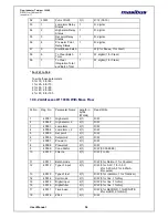
NOTE:
No
Setting
Description
No of
digit
Lo limit
Hi limit
1
Cal Zero
Zero Cal. Count
4
2
Cal Span
Span Cal. Count
5
3
Out Zero
Zero Cal. Count for
Output
4
0000
4095
4
Out Span
Span Cal Count for
Output
5
0000
4095
5
Default
Out
If user selects „yes‟,
then Out zero =
800 and Out span
(4000) is selected.
Yes/No