


User Manual
22
Flow Indicator Totaliser 1008S
REF NO: m18A/om/101
Issue No: 17
Batch Mode:
If „
Batch Mode’
(Batch nod) is selected to „Counter‟, then two parameters “
Batch
count
”(Bat cnt) and “
No of Batches”
(No_of_batch) will be displayed in Configuration
mode.
If „Batch
Mode’
is selected to „Normal‟, then two parameters will not be displayed.
Input Type:
Based on requirement, user can select input type. It will be either Voltage or Current or
Pulse.
Instrument Type:
If “
instrument type
” is set as indicator, then
Pre warn
and
Set point
parameter will not be
displayed in Program mode.
Square root:
If user selects this mode as „yes‟, flow rate will calculated using square root algorithm.
Alternatively linear calculation will be done.
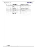
Digital Input:
If
Digital input
is selected as „yes‟ than only digital inputs will work. Four digital inputs are
there.
DIN1+: Stop Function
DIN2+: Integration (Int tot) Zero (since IT is initialize to 0, therefore batch total/roll count
are also initialized to 0)
DIN3+: Start Function
DIN4+: Batch total (bat tot) Zero
DIN-: GND (12V GND)
When any of these inputs is connected to DIN-, it will perform its specific function.
Digital Filter:
If
Digital filter
is selected as „yes‟ than in programming mode user can see „
filter
no‟
parameter. If selected
‘
no‟ then
’filter
no‟ will no be displayed
.
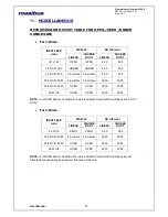
Time base:
Time base is used for calculation & display of flow rate.
Time base Setting details
Value of Integrated total for time period of t (in seconds) will be
Integration total= (flow rate * time
„t‟ in seconds)/divisor
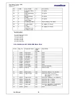
32
Rounding
2
1,2,5,10
33
Over Range
If Yes then integration total will be
running according to process value
corresponding to 20ma and if No then
integration total will stop after over limit is
reached.
-
Yes/No
34
No of Channel
To convert 3 channel Mass flow unit to 1
channel unit.
-
1-CH , 3-CH
Select
Time base
Divisor
0
Second
1
1
Minute
60 (1 x 60)
2
Hour
3600(60 x 60)
3
Day
86400(24 x 60 x 60)