6
–
+
19
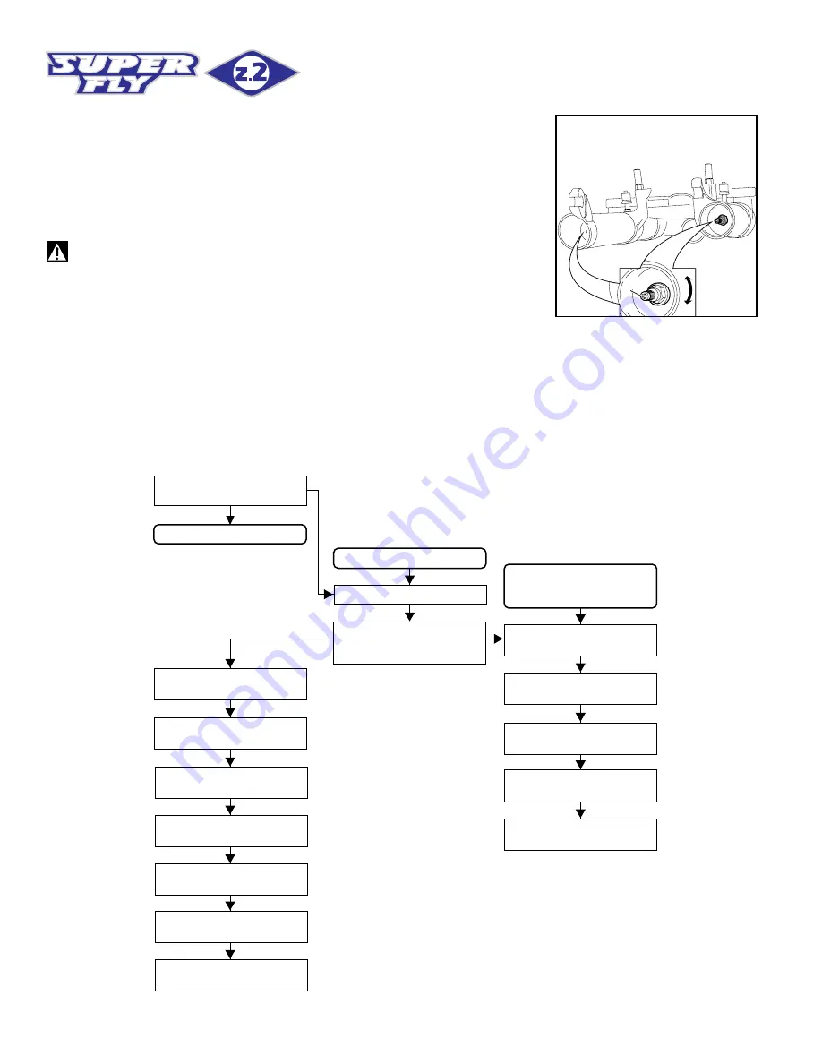
FIG. C
REBOUND ADJUSTMENT (FIG. C)
Each fork leg is equipped with an adjuster screw (19) for COMPRES-
SION and REBOUND damping. Turn the adjuster with the 2.5 mm Allen
wrench supplied with the fork. When turned, the adjuster - integral with
the inner pumping rod - will change the area in which fluid flows, thus
determining the rate of compression & rebound damping. To adjust,
always start from the minimum damping setting, i.e. with the screw fully
turned clockwise.
IMPORTANT: do not force the adjuster (19) over its limit.
DISASSEMBLY
GENERAL
– The reference numbers given in this section relate to the components shown in the fork exploded view on page 15.
– These operations refer to the fork legs having already been removed from the crown and disassembled from the brake arch.
– Before starting any operation, please read the diagram below. It shows the quickest procedure and the exact sequence in which it should be
disassembled. Locate the part you need to remove in the diagram, then look at the arrows to determine which other parts you will need to remove
first.
DISASSEMBLY DIAGRAM
PILOT BUSHING
AND SEAL ASSEMBLY
CHANGE
DUST SEAL
FIG. 5
STOP RING
FIG. 6
OIL SEAL
FIG. 7
UPPER WASHER
FIG. 8
PILOT BUSHING
FIG. 9
PUMPING ROD CHANGE
FOOT NUT FIG. 3
STANCHION TUBE WITH
WITH PUMPING ROD
FIG. 4
FOOT NUT
FIG. 1
FORK OIL CHANGE
RETAINER CUP
FIG.4
PUMPING ROD
STOP RING FIG. 11
PUMPING ROD
ASSEMBLY FIG. 12
PUMPING ROD SEALS
FIG. 13
SEAL PACK
FIG. 14
REBOUND SPRING
FIG. 14
PARKER SEALS
FIG. 15


