Martin Audio Wavefront Precision Series, User Manual
The Martin Audio Wavefront Precision Series brings exceptional audio quality to any event. Enhance your experience by accessing the comprehensive User Manual, available for free download at manualshive.com. Discover the full potential of this cutting-edge product through this detailed manual and unleash its capabilities in your next event.
Share
Download


Reviews:
No comments
Related manuals for Wavefront Precision Series

TM24I
Brand: Elkron Pages: 12

Siren
Brand: MAKS Pages: 2

WS-B1A
Brand: Yamaha Pages: 16

STAGEPAS 150M
Brand: Yamaha Pages: 2

YSP-2500
Brand: Yamaha Pages: 83

PJP-25UR
Brand: Yamaha Pages: 24

NS-40M Studio
Brand: Yamaha Pages: 7

NS-10M
Brand: Yamaha Pages: 6

NS-10M
Brand: Yamaha Pages: 14

NS-AW150
Brand: Yamaha Pages: 10

YAS-207
Brand: Yamaha Pages: 50

SR-B20A
Brand: Yamaha Pages: 8

COMPETITION ProZ4-80
Brand: µ-Dimension Pages: 7
Element
Brand: µ-Dimension Pages: 2
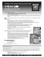
QL-K2001
Brand: Q-Logic Pages: 3

DS-50A
Brand: Roland Pages: 12

S-ALU 200
Brand: STAMOS Pages: 27

iSM1060BT
Brand: The Singing Machine Pages: 25


