background image

6

2)

When the desired setting is made, release the key and the unit will automatically store the setting after 5
seconds.

Cooling Fan Time Delay 

is factory set at 60 seconds.  When the thermostat is set in the COOL position, the

system blower will continue to circulate air for a period of 60 seconds after the compressor(s) has shut off.
This feature can be adjusted.

1)

With the system setting in the 

OFF

position, simultaneously

depress the red and blue arrow keys.  The LCD (liquid crystal dis-
play) will display the temperature differential setting.  Release the
keys and immediately press them again; the display will now show
the fan delay time in seconds.  Use the red and blue arrow keys to set the delay time to the desired set-
ting of 0, 30, or 60 seconds.

2)

When the desired setting is made, release the key and the unit will automatically store the setting after 5

seconds. 

Operating The New Thermostat

1)

Set the System switch to either the HEAT or COOL position and the Fan switch to either the AUTO or ON

position.  NOTE:  In AUTO, the system blower will run only when the A/C or heat is running.  In ON, the
system blower will operate continuously.  

2)

Use the red and blue arrow keys to select the desired temperature set point.  

3)

The LCD (liquid crystal display) displays the room tempera-

ture on the left and the set point temperature on the right.
Note:  The set point temperature may sometimes differ slight-
ly from the room temperature due to a rapidly changing room
temperature or a differential setting of 1 or 2.  

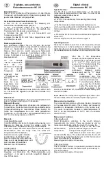
Image shows room temperature
of 78 and A/C set point of 68.

Image shows fan delay
setting at 60 seconds.

70803-IM  12/18/06  2:10 PM  Page 6

Summary of Contents for 70803

Page 1: ...INSTALLATION AND OPERATING INSTRUCTIONS Non Programmable Electronic Thermostat Heat Cool Model 70803 70803 IM 12 18 06 2 10 PM Page 1...

Page 2: ...t the system control to test the installation This will damage the thermostat and void the warranty This thermostat is equipped with automatic compressor protection to prevent damage due to short cycl...

Page 3: ...ntly depressing the bottom locking tab and swinging the back plate up and away 4 Place the back plate against the wall in the desired mounting location with the thermostat wires protruding from the wa...

Page 4: ...the battery compartment door install 2 AA Alkaline batteries included 14 Remove the clear plastic film from the display Testing The New Thermostat WARNING Do not switch the system to cool if the outd...

Page 5: ...ystem should shut down within several seconds The LCD will again display only the room temperature Programming The User Settings Temperature Differential is factory set at 5 F 0 25 C for both heating...

Page 6: ...et ting of 0 30 or 60 seconds 2 When the desired setting is made release the key and the unit will automatically store the setting after 5 seconds Operating The New Thermostat 1 Set the System switch...

Page 7: ...icates this feature has been activated Once the 5 minute delay expires the snowflake will illuminate continuously and the system will be able to re start when called upon NOTE For the purpose of unit...

Page 8: ...Blinking snowflake flame Allow the 5 minute compressor lock out to expire System turns on off Adjust the differential setting on the thermostat too frequently or A high differential decreases cycle r...

Page 9: ...I is displayed Reduce room temperature or allow a newly installed thermostat to acclimate HI indicates a room temperature reading greater than 90 F 32 C LO is displayed Increase room temperature or al...

Page 10: ...10 Wiring Diagrams Typical 5 Wire System RC RH G Y W B O Inst HEAT 24 VAC TRANSFORMER COM HOT COOL 24 VAC TRANSFORMER COM HOT FAN CONTROL COOL CONTROL HEAT CONTROL 70803 IM 12 18 06 2 10 PM Page 10...

Page 11: ...l Single Stage Heat Pump System RC RH G Y W B O Install Jumper Install Jumper C TR REV VALVE COOL ENERGIZED 24 VAC TRANSFORMER COM HOT FAN CONTROL COMPRESSOR CONTROL REV VALVE HEAT ENERGIZED 70803 IM...

Page 12: ...12 Wiring Diagrams Typical 2 Wire Millivolt System RC RH G Y W B O In C TR COM HEAT CONTROL 24 VAC TRANSFORMER HOT 70803 IM 12 18 06 2 10 PM Page 12...

Page 13: ...13 Wiring Diagrams Typical 4 Wire System RC RH G Y W B O Install Jumper C TR HEAT CONTROL COM 24 VAC TRANSFORMER HOT COOL CONTROL FAN CONTROL 70803 IM 12 18 06 2 10 PM Page 13...

Page 14: ...14 70803 IM 12 18 06 2 10 PM Page 14...

Page 15: ...ho purchased the product from a wholesaler For warranty claims consumers should contact the contractor or dealer who installed the thermostat This warranty and Motors Armatures liability does not incl...

Page 16: ...INSTALLATION AND OPERATING INSTRUCTIONS Non Programmable Electronic Thermostat Heat Cool Model 70803 70803 IM 12 18 06 2 10 PM Page 16...

Reviews: