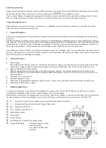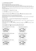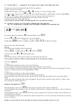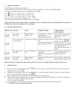
7.
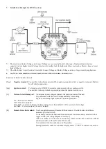
Installation (Example for 12VDC system)
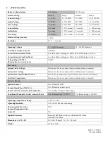
7.1 The selection of Isolate Voltage and Connect Voltage are very much affected by the type of load and relative battery
capacity. Select a higher Isolate Voltage for relatively smaller load; for high initial draw load such as Motor, choose a lower
Isolate Voltage.
7.2 Check the battery’s specifications for suitable Connect Voltage and Isolate Voltage and in cycling or standby applications.
8.
MANUAL FOR WIRING AND OPERATION OF THE CONTROL TERMINALS
Functions of the 4 Control terminals
[Neg ]
Negative terminal
: Connect this to the chassis ground of the negative grounded vehicle or negative terminal of battery
for off vehicle application..
[Ign]
Ignition control
:
To let end user to ON/OFF the isolator synchronized with car ignition switch.
Connect this to the spot which is powered up when the Ignition switch is on.
[A]
External Alert/Alarm port
: An external signal voltage to indicate the operation status of the unit.
It synchronizes with the Alert Voltage and delay time setting.
It gives out warning signal when unit is under protection.
On = The unit is connected
Off = The unit is isolated
Slow flash = to alert you the main battery voltage lower than default 12.0V or your set alert voltage.
Fast flash = Protection signal, the unit is isolated
[R]
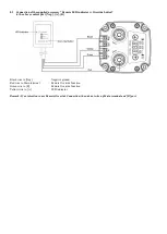
Remote Override terminal:
Use the supplied accessory Remote LED indicator w Override button which has a
momentary contact switch.
To manually connect the Main and House terminal via a momentary contact switch or
toggle switch. [see wiring diagram in section 7]
After one ‘make’ as in the case of momentary contact switch, the connection of Main
and House battery will last for about 20 seconds.
Use normal switch for continuous on/off operation.
During Remote Override On condition, display shows
to indicate connection


