5.
Operation of SSB-6113
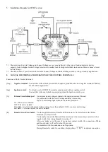
The LED display and Remote Alert signal port
Normally the display is turned off to conserve energy, press any one of the two buttons to wake up the display.
When unit is in isolated (disconnect) mode, the display shows
.
Press
Button to view Main (battery) terminal voltage
Press
Button to view House (battery) terminal voltage.
When unit is in Connected mode, the display shows
.
Only one voltage (shared by both terminals) is shown on the display.
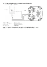
Status of the unit such as Connect, Isolate, Protection can also be remotely indicated by the supplied accessory Remote
LED Module connected to the Remote Alert signal port.
5.1 Protection Diagnosis Table
Display Icon Protection
Causes
Suggested Solution
Self-Recoverable
or Manual Reset
Over Voltage
Protection
Main Terminal
Voltage >16V
Check DC source voltage to
main terminal
.
Check load at terminal
Unit is self-recoverable when
main battery voltage lower
than 15.5V
Over Current / Over
Load Protection
Over Current >120Amp Check house battery level too
low.
Look for possible intermittent
short circuit in the wiring.
Unit is self-recoverable after 1
minute. In case of
occurs 3 times in a row, a final
protection will lock up the unit
until complete reset by
disconnect and reconnect the
battery.
Over Temperature
Protection
Unit Over Temperature
90
°
C
Check location of unit is well
ventilated.
Check cable size is sufficiently
rated.
Unit is self-recoverable when
internal temperature cool
down to below 70
°
C
Low Voltage
Protection
Main Terminal
Voltage <8V
Check main battery status and
alternator.
Unit is self-recoverable when
the main battery voltage >10V.
Remark: The above voltage setting in the table is only for 12V system, the voltage setting is double for 24V system.
6.
Installation notes:
6.1 The unit is factory default as Normal Open
. In case you want to use the unit as Normal Close, please go to the set
mode and set the unit to
6.2 The Ignition Control feature is factory default as OFF. In case you want to control the unit by car ignition switch, please go
to the set mode and set the Ignition control to
.
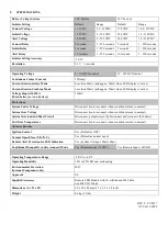
6.3 The recommended cable size is AWG#5 with 1M in length and 3% acceptable loss.
6.4 Always double check the tightness of all connections by wiggling the connected terminals and etc. Connectors and fasteners
are prone to vibration loosening in a moving vehicle.
Loosen connections cause sparks.
6.5 It is recommended to install a fuse with suitable rating connected to the battery positive terminal for safety.
!! CAUTION: Surface is hot during operation


