2-27
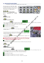
ECO
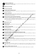
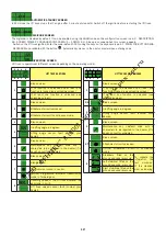
AUTOMATIC STANDBY SCREEN
In ECO mode the lift truck stops the IC engine after 1 minute at standstill. Switch off the ignition before restar ting the lift truck.
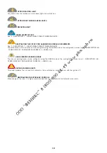
CODE 4040
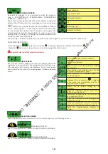
DIGICODE SCREEN
The digicode is disabled by default. It can be enabled using the ADMIN code on the configuration screen (see: 2 - DESCRIPTION:
6D - SCREEN DISPLAY: CONFIGURATION SCREEN: 4 > ADMIN: 4.2). A beep is sounded when this screen appears.
- Switch on the lift truck ignition. Enter the code (default 0000) using the keys on the keyboard (see: 6C - PANEL FOR BUTTONS AND
KEYBOARD) and validate with the button
. Automatically moves to the next character when entering code.
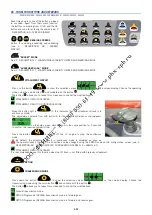
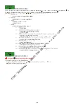
OPERATING SCREEN
Lift truck is operational (different screen depending on the operating mode).
1
2
3
4
5
6
7
8
LIFT TRUCK ON TIRES
1
Blank screen.
If no function is unlocked and at least one
function is locked (see unlocking screen).
If at least one function is unlocked (see
unlocking screen).
2
Blank screen.
Attachment circuit unlocked.
Attachment circuit in continuous mode.
3
Blank screen.
4
Jib lifting angle in degrees.
— —
Lifting angle sensor fault (contact your
dealer).
5
Blank screen.
Maintenance key + default code with 2
characters to be repor ted to the dealer (if in
doubt, consult your dealer).
6
Blank screen.
7
Blank screen.
Transmission locked in neutral.
OPTION Progressive INCHING transmission
mode in for ward gear.
8
Travelling speed of the lift truck whatever the
gear ratio in km/h.
— —
Lift truck speed sensor fault (contact your
dealer).
1
2
3
4
5
6
7
8
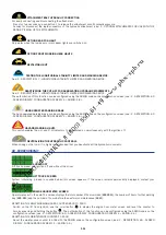
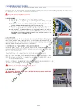
LIFT TRUCK ON STABILIZERS
1
Blank screen.
If no function is unlocked and at least one
function is locked (see unlocking screen).
If at least one function is unlocked (see
unlocking screen).
2/3
Blank screen.
4
Jib lifting angle in degrees.
— —
Lifting angle sensor fault (contact your
dealer).
5
Blank screen.
Maintenance key + default code with 2
characters to be repor ted to the dealer (if in
doubt, consult your dealer).
6/7
Blank screen.
Attachment circuit unlocked.
OPTION Attachment circuit in continuous
mode.
8
Stabilizers fitted on the
ground and under pressure.
To validate the
information, the
last movement
of the stabiliser
must be lowering.
Left stabilizer fitted on the
ground and under pressure.
Right stabilizers fitted on the
ground and under pressure.
Summary of Contents for MT 1058 R PRIVILEGE
Page 1: ......
Page 3: ......
Page 4: ...1 1 1 OPERATING AND SAFETY INSTRUCTIONS...
Page 5: ...1 2...
Page 31: ...1 28...
Page 32: ...2 1 2 DESCRIPTION...
Page 33: ...2 2...
Page 44: ...2 13...
Page 74: ...2 43...
Page 78: ...3 1 3 MAINTENANCE...
Page 79: ...3 2...
Page 84: ...3 7...
Page 92: ...3 15...
Page 104: ...3 27...
Page 116: ...4 1 4 OPTIONAL ATTACHMENTS FOR USE WITH THE RANGE...
Page 117: ...4 2...
Page 119: ...4 4...
Page 129: ...4 14...
Page 130: ...5 1 5 SPECIFIC CANADA...
Page 131: ...5 2...
Page 132: ...5 3 TABLE OF CONTENTS DIMENSIONS AND LOAD CHART MT 1058 R PRIVILEGE 5 4...
Page 135: ...5 6...
Page 136: ...6 1 6 SPECIFIC AUSTRALIA See also the operator s manual supplement 647065 AU...
Page 137: ...6 2...
Page 139: ...6 4...

