

3
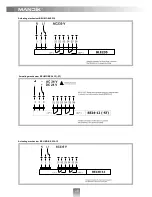
Smoke extract dampers - multi are shutters in the smoke exhaust piping systems. The dampers are
designed to remove heat and combustible products (e.g. smoke) from fire compartments. The
damper blade is controlled by actuating mechanism. The dampers are designed for using in fire
compartments that can be connected to the smoke exhaust ducts (tested according to EN 1366-8)
or they can be installed in or on the construction of the fire compartment.
Dampers are classified according to EN 13501-4.
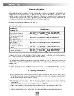
General information
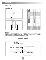
Classification of Dampers
Supporting
Construction
Classification
Horizontal duct system
EI 120 (h
od
- i o) S1000C
10000
HOT 400/30Mamulti
EI 120 (h
od
- i o) S1000C
10000
HOT 400/30AAmulti
Porous concrete ceiling
construction,
thickness 150 mm
EI 90 (h
ow
- i o) S1000C
10000
HOT 400/30AAmulti
Porous concrete wall
construction,
thickness 100 mm
EI 120 (v
ew
- i o) S1000C
10000
HOT 400/30AAmulti
Gypsum wall, thickness
100 mm
EI 120 (v
ew
- i o) S1000C
10000
HOT 400/30AAmulti
Vertical duct system
EI 120 (v
ed
- i o) S1000C
10000
HOT 400/30MAmulti
EI 120 (v
ed
- i o) S1000C
10000
HOT 400/30AAmulti
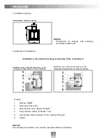
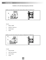
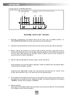
Assembly information
1. During installation the damper blade must be in position “CLOSED”. The damper body should
not be deformed in the course of bricking in. Once the damper built in, its blade should not grind
on the damper body during opening or closing.
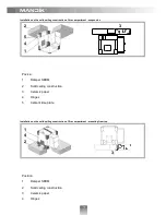
3. During installation the control mechanism must be protect against damaged and pollution.
2. The installation of more dampers into the fire separating construction must meet the following
requirements:
- the minimum distance between two dampers has to be 200 mm;
- the minimum distance between damper and construction (ceiling / wall) has to be 75 mm;
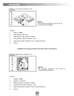
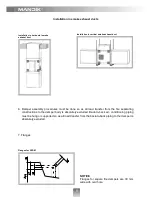
In the event of fire the Smoke and Fire Ventilation System opens the damper in the affected section
which removes combustion products and heat from this section.
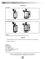
Fire dampers are suitable for installation in arbitrary position (axle of the blade as horizontal or
vertical). The Air Flow (smoke) must be directed from the control device side (see arrow on the
damper body).
Dampers are designed for macroclimatic areas with mild climate according to EN 60 721-3-3 zm.A2.