background image

3


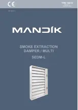
Smoke  and  heat  extraction  dampers  -  multi  are  closures  in  the  ductwork  of  smoke  extraction
devices.  In  the  event  of  a  fire,  the  smoke  and  heat  removal  system  open  the  dampers  in  the
affected section, therefore enabling the extraction fans to remove combustion products and heat
from the endangered areas.


The damper blade is controlled by an actuator.


The damper is fire resistant and is designed for systems with automatic or manual activation.


Smoke dampers are intended for use in spaces with multiple fire compartments, which can be
connected by a smoke extraction duct tested according to EN 1366-8 or can be installed in the
construction of the fire compartment.


The dampers can be supplied with flange(s) or without flange(s), with cover grille(s).


Flanges and grilles are not installed on the damper, they are supplied loose. Flanges are required
to fit the cover grilles. Grills and flanges must be installed to the dampers only after installation of
the damper into the wall.

Damper characteristics


• CE certification according to EN 12101-8


• Tested according to EN 1366-10


• Classified according to EN 13501-4 + A1


• Fire resistance according Tab. 1.3.1


• Pressure class 2 (vacuum 1000 Pa / overpressure 500 Pa)


• Tightness according to EN 1751 via body class C and via damper blade min. class 3


• C

mod

 cycling according to EN 12101-8


 • Certificate of Constancy of Properties No. 1391-CPR-2021/0009


• Performance declaration No. PM/SEDM-L/01/22/1


• Hygienic assessment of fire dampers - Report No. 1.6/pos/21/19b

In a solid wall construction and on duct in a solid wall
construction, th. 100 mm

For duct in a solid wall construction, th. 100 mm

In gypsum wall construction and on the duct in gypsum
wall construction, th. 100 mm

Summary of Contents for SEDM-L

Page 1: ......

Page 2: ...mbly operation maintenance and serviceability checks 1 Description 3 2 Design 5 3 Dimensions weights 12 4 Placement and Assembly 18 5 Statement of installations 25 6 Suspension system 37 7 Duct connec...

Page 3: ...Flanges and grilles are not installed on the damper they are supplied loose Flanges are required to fit the cover grilles Grills and flanges must be installed to the dampers only after installation o...

Page 4: ...removal dampers are activated the dampers used for air supply in the affected section open The dampers used to supply air in the affected fire section are installed at the ground The dampers are contr...

Page 5: ...cting the actuator power cable The cable entry must meet a minimum fire resistance of 30 minutes Position 1 Damper housing 2 Blades 3 Silicone blade seal 4 Internal silicone seal 5 Fire fighting foam...

Page 6: ...I III II Degree of protection IP 54 Adjustment time for 95 30 s Ambient temperature Storage temperature 30 C 55 C 40 C 80 C Connection drive auxiliary switch Cable 1 m 3 x 0 75 mm2 Cable 1 m 6 x 0 75...

Page 7: ...1 W 3 W 0 3 W 3 5 W 0 4 W Dimensioning 5 VA Imax 8 2 A 5 ms 5 5 VA Imax 8 2 A 5 ms 6 VA Imax 4 A 5 ms Protection class III III II Degree of protection IP 54 Adjustment time for 95 60 s Ambient temper...

Page 8: ...in the end position 12 W 0 5 W 8 W 0 5 W Dimensioning 18 VA Imax 8 2 A 5 ms 15 VA Imax 7 9 A 5 ms Protection class III II Degree of protection IP 54 Adjustment time for 95 60 s Ambient temperature Sto...

Page 9: ...f the actuator to the desired position The last control command will be retained even after a temporary network failure The BKNE 230 24 controls the switching position of the actuator its adjustment t...

Page 10: ...work drive terminal blocks cable 1 m without plug 6 pin plug 3 pin plug screw terminals for 2x1 5 mm2 conductor yellow flashing damper rotates to the open position yellow lit up damper is open green f...

Page 11: ...ontrol devices indicates operating condition and faults of dampers These conditions can be signalled or transmitted to the higher level control system via the auxiliary built in contacts Signals from...

Page 12: ...12 Dimensions...

Page 13: ...13 A A 30 A B 17 10 10 X A A Detail X Detail Y B B B B Y...

Page 14: ...14...

Page 15: ...08 64 8 2 9 3 0 2 0 2 7 0 2633 66 8 3 0 3 1 2 2 2 8 0 2858 70 9 3 1 3 2 2 3 2 9 0 3083 72 9 3 2 3 3 2 4 3 0 0 3308 74 9 3 3 3 4 2 5 3 2 0 3533 77 0 3 3 3 5 2 7 3 4 0 3758 79 0 3 4 3 6 2 8 3 5 0 3983 8...

Page 16: ...0 4976 110 1 4 1 4 1 3 6 4 6 0 5441 113 2 4 2 4 2 3 8 4 9 0 5906 117 3 4 2 4 3 4 0 5 1 0 6371 120 4 4 3 4 4 4 2 5 3 0 6836 123 5 4 5 4 5 4 5 5 5 0 7301 126 7 4 5 4 6 4 7 6 1 0 7766 129 8 4 6 4 7 4 9...

Page 17: ...44 153 0 5 3 5 2 5 0 6 3 0 8249 157 2 5 4 5 3 5 3 6 6 BE 40 N m 0 8954 162 1 5 4 5 4 5 5 6 9 0 9659 166 3 5 5 5 5 5 8 7 2 1 0364 170 5 5 6 5 6 6 1 7 5 1 1069 174 6 5 7 5 7 6 4 8 4 1 1774 178 8 5 8 5 8...

Page 18: ...at other objects be at least 350 mm away from the control parts of the damper Transport the damper to the installation site in the transport packaging Pay attention to the appropriate length of the fo...

Page 19: ...19...

Page 20: ...20 X Detail X Position 1 SEDM L 2 Flange Detail X Detail Y Detail Y Y...

Page 21: ...21 Position 1 SEDM L 2 Flange 3 Blades 4 Screw UNI 4x30 mm included in the flange package Fix in all holes around the perimeter of the flange...

Page 22: ...EDM L 4 Screw 5x50 mm part of SEDM L Position 1 Flange 2 Grille 3 Bolt M6x20 BN 4825 included in the grille package 4 Spacer ring included in the grille package 5 Retaining ring included in the grille...

Page 23: ...damper the damper blades must only be opened or closed by operation of the actuator only This is the BS EN1366 2 test standard distances They are considered as minimum Actual location should be based...

Page 24: ...24...

Page 25: ...25 100 Mortar or gypsum EIS 90 26 100 Ablative Coated Batt EIS 120 27 100 Ablative Coated Batt EIS 120 28...

Page 26: ...s to the fire dividing construction see chapter 6 5 and 6 6 For connection following duct see chapter 7 In case of installation damper tightly above the floor must be joint between damper body and flo...

Page 27: ...kg m3 Firestop acrylic sealant HILTI CFS S ACR or equivalent 4 Fire stop coating thickness 1 mm e g HILTI CFS CT PROMASTOP CC or equivalent 5 Flange 6 Grille A A X 100 A 100 A y min 30 mm max 400 mm...

Page 28: ...g m3 Firestop acrylic sealant HILTI CFS S ACR or equivalent 4 Fire stop coating thickness 1 mm e g HILTI CFS CT PROMASTOP CC or equivalent 5 Flange 6 Grille X Z min 30 mm max 400 mm A 100 A y y y y Z...

Page 29: ...40 to 50 mm 7 M8 bolt assemply bolt M8x105 mm 2 pcs large washer M8 nut M8 A A X X Bolts and nuts shall not prevent free rotation on the blades 100 A A 100 When installing a flange overplating strip i...

Page 30: ...e g Supalux S th 12 mm width 40 to 50 mm 7 M8 bolt assemply bolt M8x105 mm 2 pcs large washer M8 nut M8 X A A 100 A A X 100 When installing a flange overplating strip is not installed Examples of anc...

Page 31: ...orts or similar until gyp sum has fully hardened Position 1 SEDM L 2 Solid wall construction 3 British gypsum thistle bond 60 or equivalent can by used minimum density 670 kg m 4 Overplating strip e g...

Page 32: ...her M8 nut M8 9 M8 bolt assemply bolt M8x105 mm 2 pcs large washer M8 nut M8 span 200 300 mm X A y y y B B A y 100 Y 100 B B Y In case of installation damper tightly above the floor must be joint betw...

Page 33: ...OP CC or equivalent 7 Overplating strip e g Supalux S th 15 mm 8 Screw UNI 4x40 mm span 200 to 250 mm 9 Spacing strip e g Supalux S th 12 mm width 40 to 50 mm 10 M8 bolt assemply bolt M8x105 mm 2 pcs...

Page 34: ...corner front and rear with temporary block work temporary steel supports or similar until gypsum has fully hardened Position 1 SEDM L 2 Solid wall construction 3 British gypsum thistle bond 60 or equi...

Page 35: ...mm width 40 to 50 mm 10 M8 bolt assemply bolt M8x105 mm 2 pcs large washer M8 nut M8 11 Screw UNI 6x80 mm with large washer Bolts and nuts shall not prevent free rotation on the blades When installing...

Page 36: ...stop acrylic sealant HILTI CFS S ACR or equivalent 4 Overplating strip e g Supalux S th 15 mm 5 Screw UNI 4x40 mm span 200 to 250 mm 6 Spacing strip e g Supalux S th 12 mm width 40 to 50 mm 7 M8 bolt...

Page 37: ...eaded rod see chapter 6 4 The dampers and duct must be suspended separately Position 1 SEDM L 2 Duct 3 Fixing profile with threaded rod see chapter 6 4 The dampers and duct must be suspended separatel...

Page 38: ...be suspended or supported as required by the duct suppliers Threaded rods longer than 1 5 m must be protected by fire insulation Fastening threaded rods to the ceiling structure see Fig 37 Position 1...

Page 39: ...39 Position 1 SEDM L 2 Threaded rod M8 M20 3 Support HILTI MQ 41 or MQ 41 3 or equivalent 4 Bored plate HILTI MQZ L or equivalent 5 Washer for M8 M20 6 Nut M8 M20 max 50...

Page 40: ...optional accessories MANDIK a s or sheet metal min thickness 2 mm and min width 60 mm 5 Anchor to concrete min M6 6 Installation hols 7 M8 bolt assemply bolt M8x55 mm 2 pcs large washer M8 nut M8 A A...

Page 41: ...accessories MANDIK a s or sheet metal min thickness 2 mm and min width 60 mm 5 Screw UNI 6x60 mm 6 Installation hols 7 M8 bolt assemply bolt M8x55 mm 2 pcs large washer M8 nut M8 8 Gypsum grid from C...

Page 42: ...to the wall Position 1 Fixing element steel bracket for connecting damper to the wall optional accessories MANDIK a s or sheet metal min thickness 2 mm and min width 60 mm 2 Installation hols 3 M8 bol...

Page 43: ...DM L 2 Connecting air duct MULTI 3 Flange of SEDM L 4 Flange of duct 5 M8 bolt assemply bolt M8x20 mm 2 pcs large washer M8 nut M8 6 Ceramic self adhesive tape FJ 120 Pyrosil B 170 250 kg m3 Tremco il...

Page 44: ...ew min 5 mm length min 60 mm acc to min thickness protective cladding boards th 30 mm see Pos 2 max spacing 250 mm 2 SUPALUX PROMATECT L500 th min 30 mm 3 Insulation duct MULTI acc to EN 1366 8 4 Part...

Page 45: ...n p w 2 p Pa presure loss w m s air flow speed in nominal damper section kg m air density coefficient of local pressure loss for the nominal damper section see Chapter 9 Determination of pressure loss...

Page 46: ...64 0 458 0 454 0 450 0 590 0 526 0 497 0 480 0 469 0 462 0 456 0 452 0 448 0 588 0 524 0 495 0 478 0 468 0 460 0 455 0 450 0 447 0 586 0 522 0 493 0 477 0 466 0 459 0 453 0 449 0 446 0 585 0 521 0 492...

Page 47: ...0 979 0 924 0 893 0 873 0 859 0 849 0 841 0 835 1 097 0 978 0 923 0 893 0 872 0 858 0 848 0 840 0 834 2 350 2 214 2 152 2 117 2 094 2 078 2 067 2 058 2 050 2 310 2 179 2 119 2 085 2 063 2 047 2 036 2...

Page 48: ...0 901 0 851 0 823 0 805 0 792 0 782 0 775 0 769 1 010 0 900 0 851 0 822 0 804 0 791 0 781 0 774 0 768 2 251 2 126 2 069 2 037 2 016 2 001 1 990 1 982 1 975 2 215 2 094 2 039 2 007 1 987 1 973 1 962 1...

Page 49: ...3 366 3 241 3 169 3 123 3 090 3 066 3 048 3 033 3 640 3 364 3 239 3 167 3 121 3 088 3 064 3 046 3 031 4 894 4 580 4 437 4 356 4 303 4 266 4 239 4 218 4 201 4 803 4 499 4 360 4 281 4 230 4 194 4 168 4...

Page 50: ...5 36 36 37 38 38 39 39 34 35 36 36 37 38 38 39 39 34 35 36 37 37 38 38 39 39 36 37 38 39 39 40 40 41 41 37 38 39 39 40 41 41 42 42 37 38 39 40 41 41 42 42 43 38 39 40 41 41 42 42 43 43 38 39 40 41 42...

Page 51: ...51 52 53 53 54 54 55 49 50 51 52 53 53 54 54 55 49 51 52 52 53 54 54 55 55 50 51 52 53 53 54 54 55 55 49 50 51 52 53 54 54 54 55 50 51 52 53 54 54 55 55 56 51 52 53 54 54 55 56 56 56 51 53 54 54 55 56...

Page 52: ...63 64 64 65 66 66 67 61 62 63 64 65 65 66 66 67 61 62 63 64 65 65 66 66 67 61 62 63 64 65 66 66 67 67 60 62 63 64 64 65 66 66 66 61 63 64 65 65 66 66 67 67 62 63 64 65 66 67 67 68 68 63 64 65 66 67 67...

Page 53: ...76 77 77 78 79 79 79 73 75 76 77 78 78 79 79 80 74 75 76 77 78 78 79 79 80 74 75 76 77 78 79 79 80 80 71 73 74 75 75 76 76 77 77 72 73 75 75 76 77 77 78 78 73 74 75 76 77 78 78 79 79 73 75 76 77 78 78...

Page 54: ...grilles are always made of galvanised material with a powder coated coating Plastic rubber and silicone parts sealants foaming tapes seals from glass ceramic materials brass housing sheet bearings act...

Page 55: ...special pallets As standard the dampers are wrapped in plastic foil for protection during transport and must not be used for long term storage of the equipment Changes in temperature during transport...

Page 56: ...eliable function care must be taken to ensure that the closing mechanism and the bearing surfaces of the blade are not clogged with dust deposits fibrous or sticky substances and solvents Without powe...

Page 57: ...ated The operator is obliged to ensure that the damper is brought into a state where it will be able to perform its function again and during this time must provide fire protection in another sufficie...

Page 58: ...ating mechanism BEN BEE SR for 24V 65 with the communication and supply device BKNE 230 24 and actuating mechanism BEN BEE BE ST for 24V 66 Technical specifications without flange and grille flange ov...

Page 59: ...reserves the right for innovations of the product For actual product information see www mandik com MAND K a s Dob sk 550 26724 Hostomice Czech Republic Tel 420 311 706 706 E Mail mandik mandik cz ww...

Reviews: