background image

3

Terminal switch
“CLOSED”

Terminal switch
“CLOSED”

Terminal switch
“OPEN”

Damper characteristics


• CE certified acc. to EN 15650


• Tested in accordance with EN 1366­2


• Classified acc. to EN 13501­3+A1


• Fire resistance EIS 120, EIS 90


• External  Casig  leakage  class  min.  C,  Internal  leakage  class  3  (D=200  mm)  and  class  2

  (D=100 ­ 180 mm) acc. to EN 1751


• Cycling test in class C 10000 acc. to EN 15650


• Corrosion resistant acc. to EN 15650


• ES Certificate of conformity No. 1391­CPR­0089/2014
• Declaration of Perfomance No. CDM/FDMD/001/14


• Hygienic assessment of fire dampers ­ Report No. 1.6/13/16/1

Working conditions

Exact damper function is provided under the following conditions:


a) Maximum air circulation speed: 12 m.s


Maximum pressure difference: 1500 Pa


b) Dampers could be displaced into position “CLOSED” only in case that ventilator, or Air


  Handling  Unit  is  switched  off.  The  goal  is  the  securing  of  proper  closing  and  safe


  function of Fire Damper in case of Fire.


c) The  air  circulation  in  the  whole  damper  section  must  be  secured  as  steady  on  whole


  surface.


Operation of the dampers does not depend on the direction of air circulation. The dampers can


be located in an arbitrary position.

Dampers are suitable for systems without abrasive, chemical and adhesive particles.


Dampers are designed for macroclimatic areas with mild climate according to EN 60 721­3­3.


Temperature in the place of installation is permitted to range from ­ 20°C to + 50°C.


Design with mechanical control

Summary of Contents for FDMD

Page 1: ......

Page 2: ...NG 29 11 Material 29 VII INSPECTION TESTING 29 12 Inspection testing 29 VIII TRANSPORTATION AND STORAGE 29 13 Logistic terms 29 IX ASSEMBLY ATTENDANCE MAINTENANCE AND REVISIONS 29 14 Assembly 29 15 En...

Page 3: ...re separating constructions Dampers blade automatically closes air duct using a shutting spring or an actuating mechanism back spring The back spring of the actuating mechanism is started when the the...

Page 4: ...nder the following conditions a Maximum air circulation speed 12 m s Maximum pressure difference 1500 Pa b Dampers could be displaced into position CLOSED only in case that ventilator or Air Handling...

Page 5: ...ing mechanism displaces the damper blade into operation position OPEN and at the same time it pre stretches its back spring When the actuating mechanism is under voltage the damper blade is in the pos...

Page 6: ...has been exceeded After the thermal fuse Tf1 or Tf2 Tf3 has been activated the power supply is permanently and irreversibly cut off and the actuating mechanism by means of the pre stretched spring dis...

Page 7: ...drive on one hand and on the other hand it transmits the signal informing about the fire damper position OPERATION and FAILURE through 2 conductor wiring to the central Control command SWITCHED ON SWI...

Page 8: ...for use in the distribution board and displays the operation situations and failure reports of the connected fire dampers It is possible to signalise functions such as the damper position and failure...

Page 9: ...ailure reports release of the ventilators etc Tab 3 1 1 BKS 24 9A contacts K1 and K2 K1 Function Contact Situation State Current Failure 15 16 No Failure 15 16 Programming K2 Auxiliary Contact Functio...

Page 10: ...ansformer AC 24 V damper position breakdown Notice Relay contacts are drawn without power 11 b a 2 conductor wiring to BKN230 24 Control on off Reset Test External buton optional be interchanged 6 3 A...

Page 11: ...ermal protective fuse 10 Inspection hole covering 11 Limit switch CLOSED 12 Limit switch OPEN Fig 16 Fire damper FDMD design 01v2 damper with outer mechanical control and mechanical control cover Posi...

Page 12: ...2 Optional is possible use installation holders Fig 18 Fire damper FDMD with installation holders 4 3 Weights and effective area Tab 4 3 1 Weights and effective area Size D Weight kg Effective area S...

Page 13: ...nsfer from the back to back piping to the damper is absolutely excluded Installation gap must be filled by approved material perfectly in all the installation space volume installation gap To provide...

Page 14: ...otected covered against damage and pollution during installation process All fire dampers has to be closed during installation process The damper body should not be deformed in the course of bricking...

Page 15: ...m Space between damper and wall is filled by system Weichshott notice 2 EIS 90 33 Damper installed in a solid wall construction min thickness 100 mm in a gypsum wall construction min thickness 100 mm...

Page 16: ...3 Fire protection mastic Promastop P K or equal min thickness 1 mm 4 Duct Used materials example 2 Promapyr Rockwool Steprock HD 3 Promastop P K Stuffing box and fire protection mastic materials can...

Page 17: ...m with min density 800 kg m or another approved fire sealing system for damper installation 3 Duct Position 1 Fire damper FDMD 2 Stuffing box mineral stone wool min density 140 kg m or another approve...

Page 18: ...astop P K or equal min thickness 1 mm 4 Duct Used materials example 2 Promapyr Rockwool Steprock HD 3 Promastop P K Stuffing box and fire protection mastic materials can be replaced by another approve...

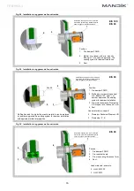
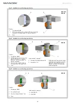
Page 19: ...tion frame D1 or D2 2 Holder Installation opening has to be reinforced around the perimeter by standard profile used for gypsum wall constructions 3 Notice Gap between fire damper body and installatio...

Page 20: ...older 3 Installation opening d D 81 mm 1 EIS 90 Installation opening has to be reinforced around the perimeter by standard profile used for gypsum wall constructions Notice Gap between fire damper bod...

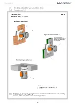
Page 21: ...trough fire separating construction or mounting by using of steel anchors Installation opening d D 10 mm d D 100 mm in the case of installation with using of concrete 1 3 3 3 4 1 Installation with us...

Page 22: ...Thickness 40 mm Notice All items are glued by PROMAT K84 and secured by screws Suspension of fire dampers has to be ensured accordingly chapter 7 Installation opening d D 100 mm 3 3 1 2 80 40 300 300...

Page 23: ...ry installation Fig 39 Battery installation solid wall construction 100 1 1 2 30 25 2 30 100 1 1 25 Position 1 Fire damper 2 Mortar or gypsum Notice Installation opening for each damper is min d D 50...

Page 24: ...and anchors 7 Suspension of fire dampers 4 5 1 6 5 1 2 120 50 Fixing boards 100 150 Permitted load of threaded rods F N by requested fire resistance 90 minutes 2 Position 1 Threaded rod M8 M20 2 Nut 3...

Page 25: ...the back to back piping to the damper is absolutely excluded Threaded rods longer than 1 5 m has to be protected by fire resistant insulation 7 3 Vertical installation Damper suspension could be made...

Page 26: ...ve and fixing rail connection by using screw or rivet 10 7 5 11 7 5 3 Position 1 Fire damper 2 Damping pad 3 Extender 4 Threaded rod 5 Fixing rail 6 Nut 7 Washer 8 Screw connection 9 Cantilever arm 10...

Page 27: ...cal pressure loss for the nominal damper section see Tab 9 1 1 1 3 7 2 Determination of pressure loss by using diagram 8 2 1 1 2 kg m 3 Diagram 8 2 1 Pressure losses for air density 1 2 kg m 3 Tab 9 1...

Page 28: ...7 3 68 7 69 9 9 45 4 50 7 53 9 56 1 59 3 61 5 63 3 66 4 68 6 70 4 71 8 73 0 10 48 1 53 5 56 6 58 9 62 0 64 3 66 0 69 1 71 4 73 1 74 5 75 7 11 50 6 56 0 59 1 61 4 64 5 66 7 68 5 71 6 73 9 75 6 77 0 78...

Page 29: ...3 9 4 3 6 4 10 1 15 6 22 7 31 5 10 5 5 4 4 1 5 9 9 4 14 6 21 5 30 11 5 9 4 1 4 5 6 8 9 13 8 20 4 28 8 12 6 2 4 3 3 9 5 3 8 4 13 1 19 5 27 6 1 Fig 44 Calculation example Given data Fire damper FDMD 20...

Page 30: ...mages when transported and manipulated During transportation the damper blade must be in the CLOSED position VI TRANSPORTATION AND STORAGE 13 2 Dampers are stored indoor in environment without any agg...

Page 31: ...checks checks according 15 1 and following checks must be carried out Check of thermal protective fuse and closing mechanism Push initiation lever lock OPEN to release the control lever and check its...

Page 32: ...lation frame D1 EIS 90 34 150 Installation frame D2 EIS 90 34 100 Installation frame D3 EIS 90 35 150 Installation frame D4 EIS 90 35 100 Battery installation EIS 90 40 Solid ceiling construction 150...

Page 33: ...trol mechanical control cover and two limit switches CLOSED OPEN 80v2 With actuating mechanism BLF 230 T 40 With actuating mechanism BLF 24 T 50 With communication and supply device BKN 230 24 and act...

Page 34: ...33 TPM 092 13...

Page 35: ...34 TPM 092 13...

Page 36: ...r vo na zm ny v robku Aktu ln informace o v robku jsou uvedeny na www mandik cz MAND K a s Dob sk 550 26724 Hostomice esk republika Tel 420 311 706 706 Fax 420 311 584 810 311 584 382 E Mail mandik ma...

Reviews: