13
Important
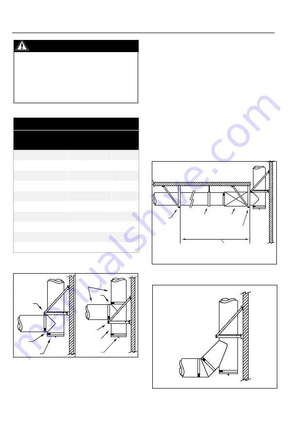
If more than 1/4” of thermal expansion is
expected between a stationary point and
the tee, the use of an expansion length
and a two axis support is recommended
to minimize bending moments on the tee
(see Figure 11 and Table 9).
Table 9
Maximum Allowable Length Between Two
Fixed Points w/o Expansion Length
Gas Temperature Rise
Maximum Length
Expansion
200
°
F
12'0''
0.25"
300
°
F
8'0''
0.25"
400
°
F
6'0''
0.25"
500
°
F
5'0''
0.25"
600
°
F
4'0''
0.25"
700
°
F
3'6''
0.25"
800
°
F
3'0''
0.25"
900
°
F
2'6''
0.25"
1000
°
F
2'0''
0.25"
Note: 60°F - 70°F ambient T°
Figure 11
Figure 12
45° tEE (t45)
1. For systems where flow resistance must
be minimized like engine or turbine exhaust.
The use of a 45° tee is suggested. It can
be combined with a 45° elbow to make a
smooth 90° turn (See Figure 12). To support
this tee, use similar method as a 90° tee.
2. When using 45° tee to connect multiple
appliances together, thermal expansion must
be considered. Thus prepared to prevent
bending moments on the tee, an expansion
length must be installed between the tees
(See Figure 13).
Figure 9
Figure 10
Wall
Support
Tee
Tee Cap or
Drain Tee Cap
Lengths
Tee
Wall
Support
Short Length
Tee Cap or
Drain Tee Cap
Stationary
Support
Suspension
Band
Expansion
Length
Stationary
Support
More than ¼" of expected
thermal expansion between two
stationary points


