22
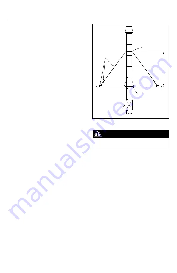
Figure 34
band on the chimney and tighten the band.
Fix the braces to the roof at 120°. Make sure
you have a rigid structure on the roof.
guy WIrE (gW)
1. The guy wire is used where the chimney
extends more than 15’ above the roof.
2. It consists of a band designed to receive 3
guy wire (supplied by others) at 120° apart
or 6 guy wire at 60° apart for diameter larger
than 24”. The guy wires are fixed to the roof by
mean of tensioner and anchor (also by others).
3. When installing guy wire, the cable must
be slightly slack or loose to allow thermal
expansion or be equipped with tensioning
springs (by others). The tensioning springs
are mandatory only when there is more than
one level of guy wire needed.
4. To minimize the effect of thermal
expansion, good practice implies installing a
fixed support and an expansion length at the
roof level (see Figure 34 ’guy wire’).
SECtIon D - rooF anD WaLL pEnEtratIonS
rooF/FLoor pEnEtratIon
1. The roof/floor penetration consist of a
firestop radiant shield (FS), a flashing (F) with
a storm collar (SC) and a floor guide (FG) or
ventilated anchor plate (APV) (see Figure 35
roof/floor penetration).
2. Those components allows the chimney
to penetrate a combustible roof or floor at 2
inches clearance to combustible. See Table 3
– Minimum openings for framing dimension.
3. The radiant shield of the firestop may need
to be trimmed to fit the height of the roof.
Nominal height is 10 inches.
4. Roof/floor penetration components are
designed to be installed on a flat roof. They
may be installed on a pitch roof if a curb is
installed to provide a flat surface.
5. Floor guide is used to protect the flashing
from lateral movement. The ventilated anchor
plate is used to protect the flashing and to
provide a re-support.
6. Do not install a chimney joint or a
expansion length in the roof/floor space.
7. For installation on non-combustibles
materials, the minimum opening can be
reduced to I.D. + 6 inches. The anchor plate can
also be used instead of the ventilated version.
8. Always seal, with outer joint sealant,
between storm collar and outer chimney
casing.
9. Installation step:
a. Cut opening to dimensions specify in Table 3.
b. Install the Firestop under the roof/floor
and attach it with screw.
c. Slide DIS / DAS chimney trough the firestop.
d. Install the floor guide or the ventilated
anchor plate on top of the roof/floor.
e. Install flashing over the chimney and the
guide/support and screw it.
f. The storm collar is placed around the
chimney and sealed to the casing with outer
Important
Cables and roof anchors designed for 30 lb.
per sq. ft. force on chimney projected area.
Guy Wire Band
H
Fixed Support
Expansion Length
Guy Cable
* tensioners and roof
anchors * (by others)


