


22
III. INSTRUCTIONS
FOR
USE
Before switching on the appliance, carefully read this
instructions manual which contains important information
about correct and optimum use of the appliance. For further
information about the oven’s features and cooking
performance, consult your local dealer.
● Do not place pans or utensils on top of the oven to avoid
obstructing the fume and steam exhaust ducts.
● Once every six mounths the burners, burner flame
uniformity and other related components must be
inspected by a qualified technician.
● Periodically (at least once a year) the appliance should
undergo a general inspection. For this purpose we
recommend taking out a service contract.
● Some models are equipped with a temperature probe
which measures the core temperature of products. This
is a precision instrument which must be handled with the
utmost care to avoid knocks or damage caused by
insertion or removal of the lead ( particularly when using
trolley-mounted units). The guarantee does not cover
damage to the temperature prob caused by improper
usage.
● When using cooking cycles with humidification, do not
exceed cooking temperatures of 200-210°C, which might
otherwise damage the oven chamber seals.
● When using the oven, leave a gap of at least 40 mm
between each container to facilitate the correct
circulation of hot air inside the oven.
The oven has a tempreature range of 30 to 300°C.
● Do not salt foods inside the oven chamber, particularly
during cooking cycles with humidification.
● Do not cook with flammable liquids such as high-alcohol
spirits.
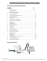
1.
DESCRIPTION OF
CONTROL PANEL
1.1.
INTRODUCTION
To facilitate familiarisation with the oven’a
functions, refer to the fold-out page at the end of
this booklet, illustrating the control panel.
The different functions available on the various
models are described below.
Some functions are common to all models while
others are only available on certain models.
1.2.
CONTROL PANEL
(refer to figure at end of booklet)
A
- Thermostat lamp
B
- Thermostat switch
C
- Timer lamp
D
-Timer switch
E
- Oveninterior cabinlight switch
F
- Steam switch (Manuel)