


20
3.
ELECTRICAL CONNECTION
● The appliance must be connected to the mains power supply
in compliance with current regulations.
● Before connecting the appliance to the mains power supply,
make sure the voltage and frequency shown on the appliance
rating plate correspond with that of the power supply.
● The appliance must be permanently connected to the mains
power supply using an H05 RN-F type cable. The power supply
cable must be protected by a maetal or rigid plastic tube. If
the appliance is connected using an existing cable, do not
insert the installation tube in the appliance. Also make sure
the tube has no sharp edges.
● An isolating switch of suitable current raiting with a contact
bearking distanceof at least 3 mm, and a 16 A delayed-action
T type fuse must be fitted upstream of the appliance. The
isolating switch must beinstalled near the appliance in the
permanent electrical system of the premises.
● The appliance must be suitably earthed. The earthing conduc-
tor must therefore be connected to the terminal marked by
the symbol on the connection terminal board.
The appliance must also be connected to an equipotential
bonding system.
This connection is made usingthe stop screw marked by the
symbol located on the outside of the appliance near the
power cable inlet.
The equipotential wire must have a minimum cross-section of
10mm
2
.
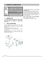
3.1
INSTALLING THE POWER SUPPLY CABLE
(Fig. “9”)
To connect the power supply cable, proceed as follows:
● Undo the two screws “V” fixing the terminal board panel
underneath the appliance on the front LH side.
● Feed the power supply cable through cable clamp inlet “B”.
● Connect the cable to terminal board “A” as shown in the
enclosed wiring diagram and fasten with the corresponding
cable clamp.
● Remount the panel and secure with the fixing screws.
The manufacturer declines any responsibility for failure to
comply with existing accident prevention standards.
4.
WATER MAINS CONNECTIONS
(Refer to the installation diagrams at the beginning of this
handbook).
Fit a mechanical fitler and shut-off cock between water inlet
pipe “C” and the mains water supply. Before connecting the
fitler, run off a certain amount of water to remove any ferrous
particles from the piping.
● The water inlet must be connected to a drinking water
supply with pressure of 150-250 kPa (1.5-2.5 bar)
4.2 WATER DRAINAGESYSTEM
Connect drain fitting “C” to a drain pipe of the same diameter
which is between 0.5 and 3 metres in lenght and is resistant to
temperatures of at least 100°C. The drain pipe must be
siphoned (height 80 mm) to an open drain “O” (“Air-Break”) or
floor grating in order to prevent any back-flow from thw sewage
system from reaching the piping inside the oven or oven
chamber.
Check the hoses and elbows on metal pipes for kinks or
pinching along the entire drain line and make sure the drain
line has a minimum gradient of 5° to prevent water collecting
inside the system.
5.
SAFETY DEVICES
The appliance is fitted with the following safety devices:
Protection fuses (see electrical wiring diagram) mounted
behind the control panel.
To replace, unscrew the cap and replace the blown fuse
with another of the same rating. The correct rating is
indicated on the corresponding fuse plate.
Oven chamber safety thermostat ( manual reset type)
mounted behind the control panel. The safety
thermostat shut off the power supply to the convection
heating system. The thermostat must only be reset by
qualified technicans after first eliminating the cause of
the fault.
Thermal cut-out inside fan motor. If the fan motor
overheats, the thermal cut-out trips and blows fuse F1,
causing the appliance to shut down (see electrical wiring
diagram).
The thermal cut-out must only be reset by qualified
technicans after first eliminating the cause of the fault
and replacing fuse F1 with another of the same rating. To
replace the fuse, open the control panel, unscrew the
cap an replace the blown fuse with another of the same
rating. The correct rating is indicated on the
corresponding fuse plate.
6.
OPERATION TEST
- Switch on the appliance following the instructions for
use.
- Test the appliance for gas leaks.
- Test the operation of the gas exhaust system.
- Test burner ignition and flame uniformity by removing
the LH side panel (where necessary) and checking the
flame through the corresponding ports.
- Using the instructions manual, explain the operation,
routine maintenance and cleaning instructions to the
user.
Important: The drain system must be installed
so that any vapours from the open drain (Air-
Break”) do not enter the aeration vents under
the appliance.
Important:
-Exercise due care since certain areas of the
oven exerior get hot during use.
-Do not cover the exhausts on top of the
appliance.