background image

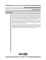
Remove 4 cover caps from end of the upper metal bar and four plugs


(36)

Attention: 

Pressing a 

red circle

 as shown below with flat headed screw driver makes more efficient to 

remove 4 plugs

(36)

.


Remove four Screws

 (33)

 (TORX Type). Therefore you are able to separate bow handle

 (16)

 from 

motor housing

 (3) 

while pulling out the interconnecting wire

 (21). 

Release four self-tapping screw

 (8) 

with Torx bit T20.


Be careful not to lose square

 (5). 

3. Exchange of Carbon brushes

Unscrew disc 4.3

(9) 

and self-tapping screw

 (17)


and then pull out the terminals with round 

nose pliers. Now you are able to pull out whole pair of brushes5*8

(2).


36 

17 

5

/ 9 

Summary of Contents for UT 1200

Page 1: ...rotection against electric shock Weight according to EPTA Procedure 01 2003 kg Power supply cord m ft No load speed min 1 rpm Max blade diameter mm 0 590 for 230V 0 550 for 110V Double insulation M14...

Page 2: ...Repair Manual UT1200 P 2 9...

Page 3: ...r Section After disconnecting the machine from the main part loosen four lens head screw 19 and remove the gearbox housing incl needle sleeve 18 from Motor Housing 3 Before continue disassembling plea...

Page 4: ...gear prepare Round bar and one set of V Block 1R258 Press down work spindle 20 with round bar in drilling direction During this procedure please take off the intermediate wheel 26 To remove grooved ba...

Page 5: ...ORX Type Therefore you are able to separate bow handle 16 from motor housing 3 while pulling out the interconnecting wire 21 Release four self tapping screw 8 with Torx bit T20 Be careful not to lose...

Page 6: ...er UT1200 III Assembly of Mixer At first Connect the intermediate wire of pair of brushes 2 to the motor 1 and place the motor in right half of motor housing 3 Please make sure that silicone plug 4 is...

Page 7: ...o not forget to replace the fitting washer 22 Press fit spindle wheel into gearbox housing 18 After setting 1set of 1R258 V block press fit shaft 27 intermediate wheel 26 and grooved ball bearing 28 P...

Page 8: ...screws 13 on wiring locking flange 14 Place cover cap 30 and screw four self tapping screws 34 and a self tapping screw 35 Place intermediate wire 21 in metal handle holder 16 while mounting it to mo...

Page 9: ...ality of the machine Test speed adjustment in different switch positions Check isolation of machine with high voltage 1500V V Grease and Glue Product Where used 1 Gearbox Grease Rhenus MSN 2 120g 4 23...

Reviews: