background image

UT1200 

I. General


(a)    The mixer should only be repaired by authorized service center. The following explanations are in 

accordance with the spare parts list UT1200. 

(b) 

     To avoid electric shock, unplug the mixer from the power supply before 
!   Attempting any service! 

II. Disassembly of Mixer
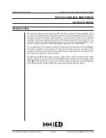
1. Motor  Section

After disconnecting the machine from the main part, loosen four lens head screw

 (19)


and remove

the gearbox housing incl. needle sleeve 

(18) 

from Motor Housing 

(3)

.

Before continue disassembling, please make sure to remove grease as shown below for efficient 
operation. Please apply grease while assembling the spare parts. 

Pair of handle can be disassembled by unscrewing four self-tapping screw

 (34)


and one self-tapping 

screw


(35)

. Open the pair of handle halves


(30) 


19 

18 

34 

35 

30 

3

/ 9 

Summary of Contents for UT 1200

Page 1: ...rotection against electric shock Weight according to EPTA Procedure 01 2003 kg Power supply cord m ft No load speed min 1 rpm Max blade diameter mm 0 590 for 230V 0 550 for 110V Double insulation M14...

Page 2: ...Repair Manual UT1200 P 2 9...

Page 3: ...r Section After disconnecting the machine from the main part loosen four lens head screw 19 and remove the gearbox housing incl needle sleeve 18 from Motor Housing 3 Before continue disassembling plea...

Page 4: ...gear prepare Round bar and one set of V Block 1R258 Press down work spindle 20 with round bar in drilling direction During this procedure please take off the intermediate wheel 26 To remove grooved ba...

Page 5: ...ORX Type Therefore you are able to separate bow handle 16 from motor housing 3 while pulling out the interconnecting wire 21 Release four self tapping screw 8 with Torx bit T20 Be careful not to lose...

Page 6: ...er UT1200 III Assembly of Mixer At first Connect the intermediate wire of pair of brushes 2 to the motor 1 and place the motor in right half of motor housing 3 Please make sure that silicone plug 4 is...

Page 7: ...o not forget to replace the fitting washer 22 Press fit spindle wheel into gearbox housing 18 After setting 1set of 1R258 V block press fit shaft 27 intermediate wheel 26 and grooved ball bearing 28 P...

Page 8: ...screws 13 on wiring locking flange 14 Place cover cap 30 and screw four self tapping screws 34 and a self tapping screw 35 Place intermediate wire 21 in metal handle holder 16 while mounting it to mo...

Page 9: ...ality of the machine Test speed adjustment in different switch positions Check isolation of machine with high voltage 1500V V Grease and Glue Product Where used 1 Gearbox Grease Rhenus MSN 2 120g 4 23...

Reviews: