background image

R

epair

P 4 / 15  

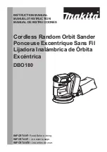
<2> Assembling gear and ball bearing

Oil seal

Bearing retainer

Apply some grease to the
inside of lip portion.

The cut portion has to be
faced to pad / disc installing side.

(1) Assemble oil seal to bearing retainer. And then, assemble spindle to the bearing retainer 
   as illustrated in Fig.4.  

Fig.4

Fig.5

Press the spindle.

(2) Assemble spindle to ball bearing 6201DDW by pressing it as illustrated in Fig.5.  

(3) Insert the spindle into gear housing as illustrated in Fig.6. And then, screw bearing retainer anti-clockwise
   into gear housing as illustrated in fig. 7.  

Bearing retainer
with oil seal

Ball bearing 
6201DDW

Ball bearing 
6201DDW

Fig.6

Bearing retainer
with oil seal

Spindle

1R043 
Wrench for Bearing retainer

Turn anti-clockwise.

Fig.7

No.1R036 Bearing Setting Plate

A : 17.2mm

A

Helical gear 

Sleeve 12

1R036 Bearing Setting
            Plate

Press

Fig.8

(4) Place the gear housing on 

No.1R036 "bearing setting plate"

  And then, assemble sleeve 12 and helical gear

    to spindle as illustrated in Fig. 8.  

Spindle

Summary of Contents for PV7000C

Page 1: ...t Max Output W 120 110 5 3 4 8 50 60 100 5 8 50 60 550 300 450 550 300 450 550 300 450 550 300 450 550 300 450 550 300 450 50 60 220 50 60 230 2 5 50 60 240 2 4 50 60 GV7000 GV7000C Polishing sanding...

Page 2: ...andard equipment for the machine may differ from country to country PV7000C PV7001C PV7001 Sanding Lock Nut Lock Nut Wrench 28 Sponge Pad 190 Wool Pad 180 Hook Loop type Abrasive Disc 180 for sanding...

Page 3: ...screws 5x40 Gear housing Gear housing cover Motor housing 1R043 Wrench for Bearing retainer Bearing retainer Fig 2 Turn clockwise 1R165 Ring Spring Setting Tool B 1R284 Round bar for arbor Spindle Bea...

Page 4: ...ted in Fig 5 3 Insert the spindle into gear housing as illustrated in Fig 6 And then screw bearing retainer anti clockwise into gear housing as illustrated in fig 7 Bearing retainer with oil seal Ball...

Page 5: ...crew 5x40 Gear housing Carbon brush Brush holder cap Motor housing Pan head screw Grounding lead wire Gear housing cover Fig 9A Gear housing cover Motor housing Baffle plate Armature Caution For effic...

Page 6: ...wire coming out from motor housing has to be passed along the motor housing and press it into the lead holder after placing its slack portion into the space for controller Switch The space for control...

Page 7: ...space for controller 3 6 2 5 Switch Green Black Color index of lead wires PV7001 grounding type equipped with 4 terminal switch without controller Grounding to be connected to gear housing Field Switc...

Page 8: ...g lead wire of noise suppressor is not used in some countries The other lead wires are as per the color index listed above Controller Choke coil for the market where the noise suppressor is required G...

Page 9: ...Grounding to be connected to gear housing Press lead wires into lead holder Pass lead wires between pin and wall Insulated terminal Pick up coil Controller Pass the lead wire of pick up coil as per t...

Page 10: ...lue The other lead wires are a per the color index listed above Grounding to be connected to gear housing This lead wire is not used in some countries Press lead wires into lead holder Pass lead wires...

Page 11: ...ller The lead wire coming out from motor housing has to be passed along the motor housing and press it into the lead holder after placing its slack portion into the space for controller Switch The spa...

Page 12: ...ransparent Color index of lead wires Noise suppressor The lead wire coming out from motor housing has to be passed along the motor housing and press it into the lead holder after placing its slack por...

Page 13: ...wires Pick up coil Controller Pass the lead wire of pick up coil as per this illustration and press them into lead holder of controller Lead holder Press the lead wires into the lead holder of contro...

Page 14: ...the market where the noise suppressor is not required Wiring diagram Pass the lead wire of pick up coil as per this illustration and press them into lead holder of controller Lead holder Press the le...

Page 15: ...r the market where the noise suppressor is required Terminal for grounding to be connected to field Pick up coil Controller Pass the lead wire of pick up coil as per this illustration and press them i...

Reviews: