background image

8

26.

Do not touch the workpiece or the offset diamond 
wheel immediately after operation; it may be 
extremely hot and could burn your skin.

27.

Check that the workpiece is properly supported.

28.

Pay attention that the wheel continues to rotate 
after the tool is switched off.

29.

Do not use the tool on any materials containing 
asbestos.

SAVE THESE INSTRUCTIONS.

 WARNING:

DO NOT let comfort or familiarity with product (gained 
from repeated use) replace strict adherence to safety 
rules for the subject product. MISUSE or failure to 
follow the safety rules stated in this instruction 
manual may cause serious personal injury.

FUNCTIONAL DESCRIPTION

 CAUTION

• Always be sure that the tool is switched off and 

unplugged before adjusting or checking function on the 
tool.

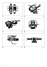
Ground Fault Circuit Interrupter (Fig. 1)

The tool is equipped with either of Ground Fault Circuit 
Interrupter (GFCI) illustrated.
Connect the tool to a power supply and test the Ground 
Fault Circuit Interrupter (GFCI) before using the tool. Push 
the RESET (R) button and confirm that the pilot lamp 
lights. Push the TEST (T) button and confirm that the pilot 
lamp goes out. Push the RESET (R) button again to use 
the tool.

 WARNING:

• Do not use the tool if the pilot lamp does not go out 

when the TEST (T) button is pushed.
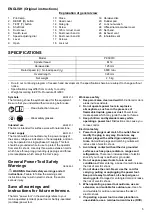
Shaft lock (Fig. 2)

 CAUTION

• Never actuate the shaft lock when the spindle is 

moving. The tool may be damaged.

Press the shaft lock to prevent spindle rotation when 
installing or removing accessories.

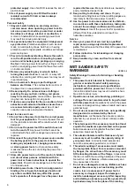
Switch action (Fig. 3)

 CAUTION

• Before plugging in the tool, always check to see that 

the switch lever actuates properly and returns to the 
“OFF” position when the rear of the switch lever is 
depressed.

To start the tool, slide the switch lever toward the “I (ON)” 
position. For continuous operation, press the front of the 
switch lever to lock it.
To stop the tool, press the rear of the switch lever, then 
slide it toward the “O (OFF)” position.

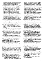
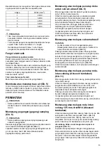
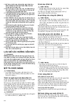
Speed adjusting dial (Fig. 4)

The rotating speed can be changed by turning the speed 
adjusting dial to a given number setting from 1 to 5.

Higher speed is obtained when the dial is turned in the 
direction of number 5. And lower speed is obtained when 
it is turned in the direction of number 1.
Refer to the table for the relationship between the number 
settings on the dial and the approximate rotating speed. 

010961

 CAUTION

• If the tool is operated continuously at low speeds, the 

motor will get overloaded and heated up.

• The speed adjusting dial can be turned only as far as 5 

and back to 1. Do not force it past 5 or 1, or the speed 
adjusting function may no longer work.

Electronic function

Constant speed control

Possible to get fine finish, because the rotating speed is 
kept constant even under the loaded condition.
Additionally, when the load on the tool exceeds 
admissible levels, power to the motor is reduced to protect 
the motor from overheating. When the load returns to 
admissible levels, the tool will operate as normal.

Soft start feature

Soft start because of suppressed starting shock.

Opening or closing of water lever (Fig. 5)

To keep the lever on the tool for water flow open, turn it to 
the position A where the water passage will be ready. 
Return it to the position B to close.

ASSEMBLY

 CAUTION

• Always be sure that the tool is switched off and 

unplugged before carrying out any work on the tool.

Installing side grip (handle) (Fig. 6)

 CAUTION

• Always be sure that the side grip is installed securely 

before operation.

Screw the side grip securely on the position of the tool as 
shown in the figure. 

(Fig. 7)

Remove one of the screws which secure gear housing 
and head cover, then screw the side grip on the tool.

Installing or removing dust cover for 
abrasive disc (Fig. 8)

When using an abrasive disc, use the 125 mm dust cover 
together.
To install the dust cover, insert the dust cover band A 
through between the tool body and the tube, and then fit it 
onto the tool. The notch of the dust cover band positions 
just below the joint.

Number

RPM (min

-1

)

1

2,000

2

3,000

3

4,500

4

6,000

5

6,800

Summary of Contents for PK5001C

Page 1: ...GB Angle Sander Instruction manual ID Mesin Pengampelas Sudut Petunjuk penggunaan VI Maùy chaø nhaùm goùc Taøi lieäu höôùng daãn TH PK5001C 012068 ...

Page 2: ...2 1 011831 2 012066 3 012070 4 010960 5 006129 6 012067 1 2 3 1 2 3 4 5 6 7 9 10 8 A B ...

Page 3: ...3 7 005588 8 012077 9 010955 10 012078 11 012071 12 012072 11 12 13 14 15 16 17 18 19 20 21 4 22 17 23 21 4 ...

Page 4: ...4 13 012076 14 010958 15 012069 16 006105 24 25 ...

Page 5: ...s gases or dust Power tools create sparks which may ignite the dust or fumes 3 Keep children and bystanders away while operating a power tool Distractions can cause you to lose control Electrical safety 4 Power tool plugs must match the outlet Never modify the plug in any way Do not use any adapter plugs with earthed grounded power tools Unmodified plugs and matching outlets will reduce risk of el...

Page 6: ...binding of moving parts breakage of parts and any other condition that may affect the power tool s operation If damaged have the power tool repaired before use Many accidents are caused by poorly maintained power tools 23 Keep cutting tools sharp and clean Properly maintained cutting tools with sharp cutting edges are less likely to bind and are easier to control 24 Use the power tool accessories ...

Page 7: ...result of power tool misuse and or incorrect operating procedures or conditions and can be avoided by taking proper precautions as given below a Maintain a firm grip on the power tool and position your body and arm to allow you to resist kickback forces Always use auxiliary handle if provided for maximum control over kickback or torque reaction during start up The operator can control torque react...

Page 8: ...ion Speed adjusting dial Fig 4 The rotating speed can be changed by turning the speed adjusting dial to a given number setting from 1 to 5 Higher speed is obtained when the dial is turned in the direction of number 5 And lower speed is obtained when it is turned in the direction of number 1 Refer to the table for the relationship between the number settings on the dial and the approximate rotating...

Page 9: ...dust could result in electric shock fire and or property damage CAUTION Always wear safety goggles or a face shield during operation Never switch on the tool when it is in contact with the workpiece it may cause an injury to operator Always use the abrasive disc together with the rubber pad Using the rubber pad by itself may seriously damage the rubber pad When using the abrasive disc make sure th...

Page 10: ... are recommended for use with your Makita tool specified in this manual The use of any other accessories or attachments might present a risk of injury to persons Only use accessory or attachment for its stated purpose If you need any assistance for more details regarding these accessories ask your local Makita Service Center Abrasive discs wet type Side grip Rubber pad Lock nut Lock nut wrench 125...

Page 11: ... berantakan atau gelap mengundang kecelakaan 2 Jangan mengoperasikan mesin listrik dalam atmosfer yang mudah meledak seperti bila ada cairan gas atau debu mudah menyala Mesin listrik menimbulkan percikan api yang dapat menyalakan debu atau uap tersebut 3 Jauhkan anak anak dan orang lain saat menggunakan mesin listrik Bila perhatian terpecah Anda dapat kehilangan kendali Keamanan kelistrikan 4 Stek...

Page 12: ...yang tepat akan menuntaskan pekerjaan dengan lebih baik dan aman pada kecepatan sesuai rancangannya 19 Jangan gunakan mesin jika saklar tidak bisa menghidupkan atau mematikannya Mesin listrik yang tidak dapat dikendalikan dengan sakelarnya adalah berbahaya dan harus diperbaiki 20 Cabut steker dari sumber listrik dan atau baterai dari mesin listrik sebelum melakukan penyetelan penggantian aksesori ...

Page 13: ...ebut 12 Jangan sekali kali meletakkan mesin listrik sebelum aksesori berhenti sepenuhnya Aksesori yang berputar dapat tersangkut pada permukaan dan menarik mesin listrik lepas dari kendali Anda 13 Jangan menyalakan mesin listrik saat membawanya di sisi tubuh Anda Kontak tak disengaja dengan aksesori yang berputar dapat menggulung pakaian Anda dan menarik aksesori ke tubuh Anda 14 Bersihkanlah luba...

Page 14: ...up Jalankan mesin hanya ketika digenggam tangan 26 Jangan menyentuh benda kerja atau roda intan cekung segera setelah pengoperasian suhunya mungkin sangat panas dan dapat membakar kulit Anda 27 Pastikan bahwa benda kerja ditopang dengan baik 28 Perhatikan bahwa roda masih akan terus berputar setelah mesin dimatikan 29 Jangan menggunakan mesin pada bahan yang mengandung asbes SIMPAN PETUNJUK INI PE...

Page 15: ...posisikan tepat di bawah sambungan Atur penutup debu sehingga takik penutup debu terpasang pas ke tonjolan pada boks bantalan Kencangkan pengikat penutup debu B dengan mengencangkan sekrup sekrupnya dengan kuat Untuk melepaskan penutup debu ikuti prosedur pemasangan secara terbalik Memasang atau melepas cakram abrasif CATATAN Gunakan aksesori mesin pengampelas yang dideskripsikan dalam buku petunj...

Page 16: ...ukan pemeriksaan atau perawatan PEMBERITAHUAN Jangan sekali kali menggunakan bensin tiner alkohol atau bahan sejenisnya Penggunaan bahan demikian dapat menyebabkan perubahan warna dan bentuk serta timbulnya retakan Gb 15 Mesin dan lubang ventilasi udaranya harus dijaga kebersihannya Bersihkanlah lubang ventilasi udara mesin ini secara teratur atau kapan pun aliran udara mulai terhambat Mengganti s...

Page 17: ... boän hoaëc toái coù theå daãn ñeán tai naïn 2 Khoâng vaän haønh duïng cuï maùy trong moâi tröôøng chaùy noå ví duï nhö moâi tröôøng coù söï hieän dieän cuûa caùc chaát loûng khí hoaëc buïi deã chaùy Caùc duïng cuï maùy taïo ra tia löûa ñieän coù theå laøm buïi hoaëc khí boác chaùy 3 Giöõ treû em vaø ngöôøi ngoaøi traùnh xa nôi laøm vieäc khi ñang vaän haønh duïng cuï maùy Söï sao laõng coù theå k...

Page 18: ...ù Moïi duïng cuï maùy khoâng theå ñieàu khieån ñöôïc baèng coâng taéc ñeàu raát nguy hieåm vaø caàn ñöôïc söûa chöõa 20 Ruùt phích caém ra khoûi nguoàn ñieän vaø hoaëc thaùo boä pin khoûi duïng cuï maùy tröôùc khi thöïc hieän baát kyø coâng vieäc ñieàu chænh thay ñoåi phuï tuøng hay caát giöõ duïng cuï maùy naøo Nhöõng bieän phaùp an toaøn phoøng ngöøa naøy seõ giaûm nguy cô khôûi ñoäng voâ tình d...

Page 19: ...m loaïi daïng boät coù theå gaây ra caùc nguy cô veà ñieän 15 Khoâng vaän haønh duïng cuï maùy gaàn caùc vaät lieäu deã chaùy Tia löûa ñieän coù theå laøm chaùy nhöõng vaät lieäu naøy Löïc ñaåy ngöôïc vaø caûnh baùo lieân quan Löïc ñaåy ngöôïc laø phaûn öùng baát ngôø khi ñóa maøi taám ñôõ choåi ñang quay hoaëc baát kyø phuï tuøng naøo khaùc bò keït hoaëc bò vöôùng Vieäc keït hoaëc vöôùng coù theå...

Page 20: ...T LAÏI vaø xaùc nhaän raèng ñeøn baùo saùng Nhaán nuùt TEST T KIEÅM TRA ñeå xaùc nhaän raèng ñeøn baùo taét Nhaán laïi nuùt RESET R ÑAËT LAÏI ñeå söû duïng duïng cuï CAÛNH BAÙO Khoâng söû duïng duïng cuï naøy neáu ñeøn baùo khoâng taét khi nhaán nuùt TEST T KIEÅM TRA Khoaù truïc Hình 2 THAÄN TROÏNG Khoâng ñöôïc vaän haønh khoaù truïc khi truïc quay ñang chuyeån ñoäng Duïng cuï coù theå bò hoûng AÁ...

Page 21: ...õm taâm haõy nhaán khoaù truïc ñaët chìa vaën ñai oác haõm vaøo loã cuûa ñóa vaø xoay ngöôïc chieàu kim ñoàng hoà Trong tröôøng hôïp caùc loã naøy khoâng vöøa vôùi chìa vaên ñai oác haõm Hình 13 Thaùo taám che ôû caïnh tröôùc baèng caùch tröôït taám che Sau ñoù nhaán khoaù truïc vaø giöõ hai maët phaúng song song cuûa ñóa kim cöông loõm taâm baèng chìa vaën vaø xoay ñóa Neáu baïn khoâng nhìn thaáy...

Page 22: ...h beân trong duïng cuï Khoâng töï thaùo hoaëc laøm saïch beân trong duïng cuï Chuùng toâi luoân khuyeân baïn neân yeâu caàu laøm saïch sôùm Ñeå duy trì ÑOÄ AN TOAØN vaø ÑOÄ TIN CAÄY cuûa saûn phaåm vieäc söûa chöõa kieåm tra vaø thay choåi than cuõng nhö moïi baûo döôõng hoaëc ñieàu chænh khaùc ñeàu phaûi do Trung taâm Baûo trì Ñöôïc uyû quyeàn cuûa Makita thöïc hieän luoân söû duïng caùc boä phaä...

Page 23: ...6 5 AC 2 5 1 7 8 6 557 19 1 557 1 557 1 2 5 GEA005 3 8 557 19 5 9 557 62 557 1 557 557 1 1 2 2 0 1 2 34 5 0 1 5 6 2 RESET R 3 TEST T 4 9 5 6 10 7 9 8 9 10 11 12 13 14 125 15 6 A 16 6 B 17 18 9 9 19 20 21 9 9 22 1 5 9 23 6 24 1 25 1 PK5001C M14 125 9 n 9 n0 6 800 1 328 4 2 5 ...

Page 24: ...0 1 557 19 8 0 1 3 557 1 9 9 RCD 1 RCD 557 1 10 5 RCD 30 mA 0 11 1 1 557 9 12 0 0 7 1 3 3 7 1 3 1 9 13 0 0 0 10 6 557 1 0 5 557 10 14 0 0 1 557 9 15 557 2 6 0 16 0 5 5 1 17 0 6034 0 1 9 1 18 3 0 557 43 3 6 19 557 1 10 20 8 0 0 60 4 7 3 1 1 557 21 60 6 0 0 557 A 22 0 0 7 5 0 2 2 557 6 23 0 6 B ...

Page 25: ...9 5 9 2 0 1 6 0 9 3 00 C 5 5 0 6 557 9 1 3 4 6 0 6 0 0 B 0 9 9 1 9 5 5 D 6 7 0 6 6 0 0 0 5 D 0 0 0 2 557 7 0 C 0 5 0 0 0 0 0 0 0 0 6 0 1 1 8 0 0 34 34 D D 5 6 7 1 7 6 7 1 2 C 7 6 3 9 C 9 0 0 0 1 0 9 9 10 0 0 C 5 0 2 1 5 557 557 557 8 6 557 19 11 5 6 6 6 2 0 12 0 6 2 557 13 0 2 2 0 ...

Page 26: ...6 6 1 7 a 0 0 0 0 6 0 0 8 6 8 1 7 b 0 c 0 d B D 0 0 0 0 e 0 2 0 00 E 0 C a 0 0 3 0 00 C 0 0 557 6 7 3 0 C a 5 5 5 5 6 16 0 0 00 26 00 9 C 17 0 34 18 0 0 GFCI E 0 0 00 GFCI 2 19 6 0 20 6 6 21 0 5 0 6 22 C 8 0 00 2 0 0 8 2 2 C 23 0 5 5 0 24 0 0 6 0 25 26 5 0 0 00 26 6 5 27 0 28 0 29 0 0 ...

Page 27: ...5 GFCI RESET R 5 6 TEST T 5 6 RESET R 1 1 5 6 TEST T 2 9 1 9 7 6 0 3 10 OFF 10 10 I 10 9 10 O 4 9 6 9 1 62 5 9 2 5 9 1 62 40 9 9 010961 1 9 0 9 6 5 1 E 5 1 5B 01 9 6 1 00 0 6 9 3 3 557 0 6 7 0 3 0 2 5 0 0 1 5 A B 10 6 C 1 1 2 000 2 3 000 3 4 500 4 6 000 5 6 800 ...

Page 28: ...9 9 9 9 6 1 9 9 9 F 10 6 8 2 3 11 1 1 5 9 1 5 9 1 5 9 6 2 6 2 1 5 9 6 6 1 5 9 8 2 3 125 M14 1 5 9 9 1 5 9 12 6 1 5 9 9 9 9 9 F 0 6 6 13 6 9 1 1 5 9 9 1 5 9 6 0 00 2 O 2 34 0 0 0 00 26 00 9 1 9 D 557 19 5 0 7 10 1 8 9 1 1 1 1 1 1 5 9 1 5 9 9 10 6 10 1 14 1 15 1 1 9 1 2 ...

Page 29: ...5 9 1 5 9 1 9 43 6 10 6 3 1 1 0 G 0 3 15 1 1 1 16 1 1 3 1 9 1 6 1 1 1 3 3 43 19 1 0 Makita 3 6 3 C 3 H0 3 3 H0 0 Makita 0 C 1 Makita 1 0 Makita 1 0 1 9 1 0 0 6 0 Makita 1 D 9 9 9 9 1 125 1 5 9 1 1 5 9 0 0 I 1 ...

Page 30: ...30 ...

Page 31: ...31 ...

Page 32: ...ALA Makita Corporation Anjo Aichi Japan 884956 370 www makita com ...

Reviews: