P
7
/1
6
R
epair
[3] DISASSEMBLY/ASSEMBLY
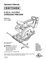
[3] -4. Angular Guide
Fig. 6
DISASSEMBLING
Angular guide can be disassembled as described in
Fig. 6
.
Assemble Angular guide by taking the reverse step of Disassembling. (
Fig. 6
)
M5 Truss
head screw
O Ring 9
Stopper
Angular guide
4. Hold M5-8 Hex lock nut with Wrench 8,
then unscrew M5 Truss head screw
O ring 9 and Stopper can now be removed.
5. Disassemble Angular guide.
M5-8
Hex lock nut
Angular guide
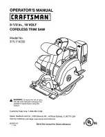
ASSEMBLING
Note:
1. E-8 Bow stop ring must be mounted as shown on the
left
in
Fig. 2A
.
2. Adjust Lever 45 as shown on the
right
in
Fig. 2A
.
1. Loosen M6x20 Hex bolt
with Lever 45, then remove
E-8 Bow stop ring.
2. Remove M6x20 Hex bolt
by using Lever 45 as a tool,
then remove Flat washer 6.
3. Loosen M6x8 Hex socket head set crew,
then remove Shoulder pin 6-7 that
functions as a hinge.
Lever 45
M6x20 Hex bolt
Flat washer 6
M6x8 Hex socket
set screw
Shoulder pin 6-7
E-8 Bow stop ring
Lever 45
M6x20 Hex bolt