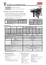
background image

C

ircuit diagram

P 12 / 12 

Black

White

Orange

Purple

Color index of lead wires

1

2

3

4

5

Field

Receptacle

Receptacle

Switch

Power supply cord

Noise 
suppressor

W

iring diagram

Handle side 

Rear cover side

Lead wire
(orange)

Lead wire
(purple)

Inside of motor housing 

Handle section

Connect receptacles to brush holders
so that the lead wires of orange and
purple face to the rear cover side 
as illustration.

Motor housing

Do not slack the
lead wires in this
portion.

Put 2 lead wires in every lead holder.

Noise suppressor
or sponge, which are
not used in some countries.

Summary of Contents for HM1304

Page 1: ...l be effective from 2006 Demolition Hammer TECHNICAL INFORMATION CONCEPTION AND MAIN APPLICATIONS Specification Standard equipment Optional accessories Note The standard equipment for the tool shown m...

Page 2: ...and striker reciprocate 0 5 0 02 MAKITA grease R No 00 12 13 O Rings 61 0 5 0 02 MAKITA grease R No 00 15 X Ring 30 0 5 0 02 MAKITA grease R No 00 22 O Ring 44 0 5 0 02 MAKITA grease R No 00 19 O Rin...

Page 3: ...wires See Fig 3 3 Unscrew hex socket head bolt M6x50 See Fig 4 4 Strike crank housing as illustrated in Fig 5 Then motor housing can be separated from crank housing See Fig 5 5 Strike crank housing a...

Page 4: ...sure that flat washer 18 has been previously mounted in the bearing assembling hole of motor housing rear cover side Mount motor housing to crank housing by pressing Fasten it with hex socket head bo...

Page 5: ...which connecting rod and crank shaft are connected See Fig 12 3 Take off hex socket head bolt M6x16 flat washer 6 and needle bearing 1715 Then gear housing including helical gear 57 helical gear 34 cr...

Page 6: ...Put No 1R201 Jig for Retainer Ring on retainer ring and pass No 1R282 Round Bar for Atbor through the screw hole for hex socket head bolt M8x30 Press the round bar for arbor with arbor press so retain...

Page 7: ...illustrated in Fig 23 7 Assembling tool retainer section Fig 18 Fig 19 Fig 20 Fig 21 Fig 22 Fig 23 Spring pin extractor Spring pins 8 40 Tool retainer pole Tool retainer Tool holder Tool retainer sha...

Page 8: ...ing 67 has been previously mounted to crank housing Piston Connecting rod Needle bearing 1715 Flat washer 6 Hex socket head bolt M6x18 Make sure that these pins 6 have been previously mounted to the i...

Page 9: ...al gear 57 Helical gear 57 Gear housing Gear housing Gear housing 2 x Round bar for arbor with 30mm Helical gear 57 Ring 25 Hex socket bolts M6x22 Ball bearing 6205LLU Bearing box 10 Assembling gear h...

Page 10: ...k shaft by pressing crank shaft with arbor press See Fig 37 6 Assemble helical gear 34 to which ball bearings 6001 and 6201 have been previously mounted to gear housing See Fig 38 Woodruff key 4 Groov...

Page 11: ...pcs Hex socket head bolt M10x40 4 pcs Hex socket head bolt M6x22 4 pcs Hex socket head bolt M6x50 4 pcs Hex socket head bolt M6x45 4 pcs Hex socket head bolt M6x50 2 pcs Hex socket head bolt M6x40 2 p...

Page 12: ...side Rear cover side Lead wire orange Lead wire purple Inside of motor housing Handle section Connect receptacles to brush holders so that the lead wires of orange and purple face to the rear cover si...

Reviews: