background image

P  3/ 17

R

epair

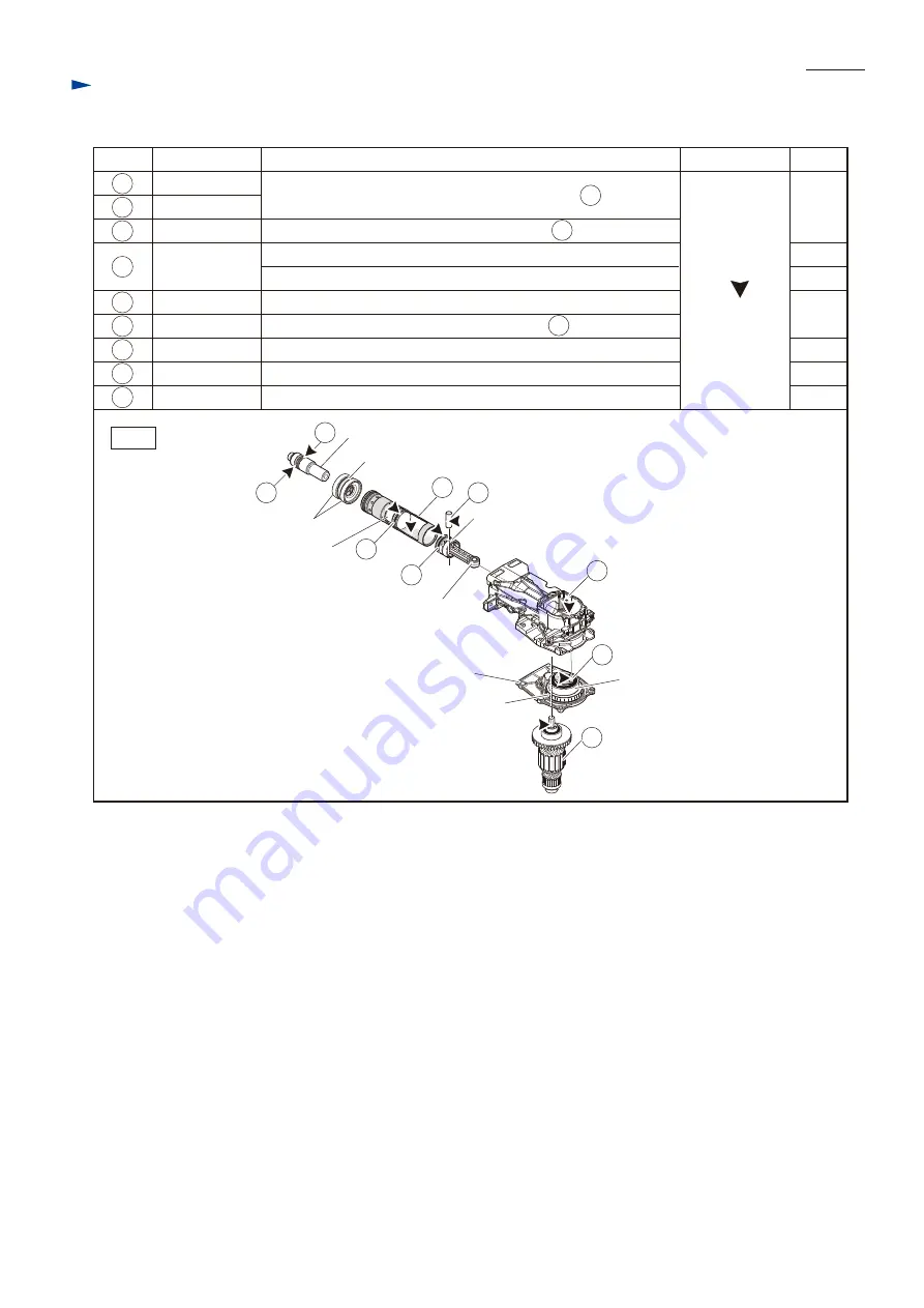
[2] LUBRICATIONS (cont.)

Makita grease R

No. 00

Item No.

Description

Portion to lubricate for Impact bolt section and Crank section 

Amount

Lubricant

36 37

38

34

62

66

77

37

36

34

38

Pin 12

Cylinder 40

O ring 44

O ring 31.5
Crank housing
Crank shaft
Armature

Whole portion

Space between Piston and Striker
Space between Impact bolt and Striker

Whole portion for smooth action of Striker in  36  Cylinder 40

Whole portion for smooth action of Impact bolt in  24 Tool holder

Whole portion for smooth action of Piston in  36  Cylinder 40
Space where Helical gear 57 and Crank shaft rotate
Pin portion where Connecting rod accepts
Drive end (Gear portion)

62
66
77

25

26 Impact bolt

Helical gear 57

Gear housing

Rubber ring 24

Ball bearing 6206LLU

Shoulder sleeve

Piston

Striker

25
26

X ring 21
Fluoride ring 28

40g

10g

a little

a little

a little

10g
10g

Connecting rod

Fig. 2

Summary of Contents for HM1205C

Page 1: ...tection from electric shock No No No With Side handle Note The standard equipment for the tool shown above may vary by country PRODUCT CONCEPT AND MAIN APPLICATIONS HM1205C Demolition Hammer Model HM1...

Page 2: ...sembling Helical gear 1R258 V Block accepting Helical gear 57 when removing Crank shaft 1R263 Bearing Extractor separating Motor section from Crank housing 1R269 Bearing Extractor removing Ball bearin...

Page 3: ...lt and Striker Whole portion for smooth action of Striker in 36 Cylinder 40 Whole portion for smooth action of Impact bolt in 24 Tool holder Whole portion for smooth action of Piston in 36 Cylinder 40...

Page 4: ...ss down Flat washer 30 with 1R363 and remove Ring spring 26 with 1R003 212 Note For easy and safety disassembling stand the machine on Work bench as drawn below And remove Tool holder cap with a slott...

Page 5: ...spring 56 Change ring cover Chuck mechanism can be removed in this step Spring guide Compression spring 56 Change ring cover Retaining ring WR 45 Change ring Change ring Retaining ring WR 45 Change r...

Page 6: ...rated from Crank housing without disassembling Chuck mechanism Barrel section Crank housing Shoulder sleeve Impact bolt Tool holder cap Rubber ring 24 Housing cover M8x35 Hex socket head bolt 4pcs M5x...

Page 7: ...ng 23 together with Fluoride ring 28 and X ring 21 with new ones 2 If there is dust in Tool holder wash it off 3 Once Fluoride ring 28 deforms it does not shrink by itself If installing it into Impact...

Page 8: ...14 Ring spring 35 Tool holder Tool holder Tool holder Rubber ring 39 Flat washer 39 O ring 35 5 Barrel complete O ring 35 5 1R003 212 Assemble Tool holder section by reversing the disassembly procedu...

Page 9: ...to remove Armature from machine Fig 16 Fig 15 Controller Slotted screwdriver 4x14 Tapping screw 2pcs 1 Loosen two 4x14 Tapping screws And pry off Controller with two slotted screwdrivers 3 Detach Spi...

Page 10: ...from Motor housing with two 1R263 Note Flat washer 15 may come off So be careful not to lose it Fig 18 6 Disassemble Crank section as drawn in Figs 18 19 and 20 1 Disassemble Gear housing complete wi...

Page 11: ...t Ball bearing 6206LLU Helical gear 57 Connecting rod Crank housing Piston Flat washer 12 2 Tap Crank housing as drawn below Crank shaft is removed together with Ball bearing 6206LLU Helical gear 57 a...

Page 12: ...r Helical gear 57 Fig 23 Fig 24 2 Assemble Crank shaft section to Crank housing as drawn in Figs 25 and 26 3 Assemble components by reversing the disassembly steps 6 to 1 Refer to Figs 18 17 16 and 15...

Page 13: ...ove Armature as drawn in Fig 27 Assemble Armature by reversing the disassembly procedure Note Make sure that Flat washer 15 is set in place Refer to Fig 17 Fig 27 2 Remove Ball bearing 6000DDW with 1R...

Page 14: ...crews and remove Handle cover DISASSEMBLING Power supply cord Switch lever Lever stopper 4x18 Tapping screw 2pcs Terminal block Switch Handle cover Sponge sheet Rubber pin 4 green 2 Electrical parts S...

Page 15: ...es it is recommended to replace the following parts at the same time for longer service life of the machine Refer to Fig 30 2 Be sure to apply the appropriate greases to the specific portions Refer to...

Page 16: ...side Wrong Motor housing Motor housing Wiring of Carbon brush Insert Carbon brush into Brush holder as drawn in Fig D 2 Note The pig tail should not be faced to Rear cover side This Lead wire is brow...

Page 17: ...o Controller Lead wire holder Terminal block Lead wire holder covered with Sponge sheet Switch Switch The following Lead wires have to be routed over Lead wire thin black and to be routed through Lead...

Reviews: