background image

6 ENGLISH

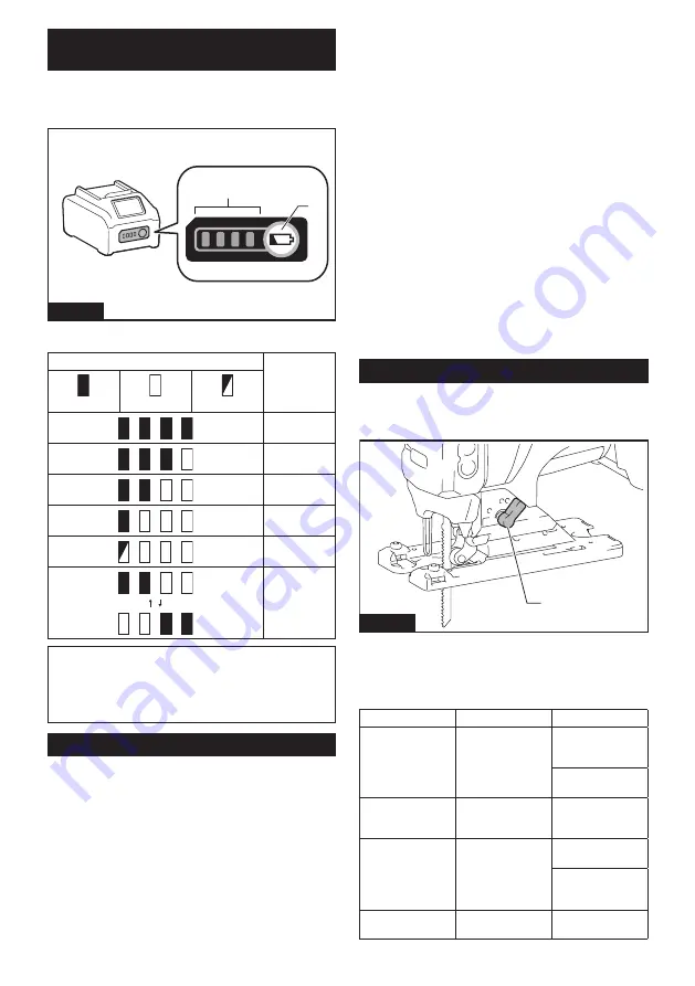
Indicating the remaining battery 

capacity

Press the check button on the battery cartridge to indi-

cate the remaining battery capacity. The indicator lamps 

light up for a few seconds.

1

2

Fig.2

►     

1.

 Indicator lamps 

2.

 Check button

Indicator lamps

Remaining 

capacity

Lighted

Off

Blinking

75% to 100%

50% to 75%

25% to 50%

0% to 25%

Charge the 

battery.

The battery 

may have

malfunctioned.

NOTE:

 Depending on the conditions of use and the 

ambient temperature, the indication may differ slightly 

from the actual capacity.

NOTE:

 The first (far left) indicator lamp will blink when 

the battery protection system works.

Tool / battery protection system

The tool is equipped with a tool/battery protection sys-

tem. This system automatically cuts off power to the 

motor to extend tool and battery life. The tool will auto-

matically stop during operation if the tool or battery is 

placed under one of the following conditions:

Overload protection

When the battery is operated in a manner that causes 

it to draw an abnormally high current, the tool automat-

ically stops without any indication. In this situation, turn 

the tool off and stop the application that caused the tool 

to become overloaded. Then turn the tool on to restart.

Overheat protection

When the tool or battery is overheated, the tool stops 

automatically and the lamp blinks. In this case, let the 

tool and battery cool before turning the tool on again.

Overdischarge protection

When the battery capacity is not enough, the tool stops 

automatically. In this case, remove the battery from the 

tool and charge the battery.

Protections against other causes

Protection system is also designed for other causes that could 

damage the tool and allows the tool to stop automatically. 

Take all the following steps to clear the causes, when the tool 

has been brought to a temporary halt or stop in operation.
1. 

Turn the tool off, and then turn it on again to restart.

2.  Charge the battery(ies) or replace it/them with 

recharged battery(ies).

3.  Let the tool and battery(ies) cool down.
If no improvement can be found by restoring protection 

system, then contact your local Makita Service Center.

Selecting the cutting action

This tool can be operated with an orbital or a straight line (up 

and down) cutting action. The orbital cutting action thrusts the 

jig saw blade forward and increases cutting speed.

1

Fig.3

►     

1.

 Cutting action changing lever

To change the cutting action, turn the cutting action 

changing lever to the desired cutting action position. 

Refer to the table to select the appropriate cutting action.

Position

Cutting action

Applications

0

Straight line cutting 

action

For cutting mild 

steel, stainless 

steel and plastics.
For clean cuts in 

wood and plywood.

I

Small orbital 

cutting action

For cutting mild 

steel, aluminum 

and hard wood.

II

Medium orbital 

cutting action

For cutting wood 

and plywood.
For fast cutting in 

aluminum and mild 

steel.

III

Large orbital 

cutting action

For fast cutting in 

wood and plywood.

Summary of Contents for GVJ01Z

Page 1: ...INSTRUCTION MANUAL MANUAL DE INSTRUCCIONES Cordless Jig Saw Sierra Caladora Inal mbrica GVJ01 IMPORTANT Read Before Using IMPORTANTE Lea antes de usar...

Page 2: ...ference The term power tool in the warnings refers to your mains operated corded power tool or battery operated cordless power tool Work area safety 1 Keep work area clean and well lit Cluttered or da...

Page 3: ...e power tool before making any adjust ments changing accessories or storing power tools Such preventive safety measures reduce the risk of starting the power tool accidentally 4 Store idle power tools...

Page 4: ...work ing with SAVE THESE INSTRUCTIONS WARNING DO NOT let comfort or familiarity with product gained from repeated use replace strict adherence to safety rules for the subject product MISUSE or failure...

Page 5: ...stop tool operation and charge the battery cartridge when you notice less tool power 2 Never recharge a fully charged battery car tridge Overcharging shortens the battery service life 3 Charge the bat...

Page 6: ...ning the tool on again Overdischarge protection When the battery capacity is not enough the tool stops automatically In this case remove the battery from the tool and charge the battery Protections ag...

Page 7: ...s the tool into standby mode too About 3 seconds after you start pressing the lock switch the brightness of the lamp will be minimized and the brightness will not change after that NOTE The brightness...

Page 8: ...EMBLY CAUTION Always be sure that the tool is switched off and the battery cartridge is removed before carrying out any work on the tool Installing or removing jig saw blade CAUTION Always clean out a...

Page 9: ...blade NOTE Occasionally lubricate the roller Hex wrench storage When not in use store the hex wrench as shown in the figure to keep it from being lost 1 2 Fig 10 1 Base 2 Hex wrench Cover plate Use th...

Page 10: ...ld the base flush with the workpiece Failure to do so may cause jig saw blade breakage resulting in a serious injury CAUTION Advance the tool very slowly when cutting curves or scrolling Forcing the t...

Page 11: ...wrench 2 Bolt 3 Base Cutouts Cutouts can be made with either of two methods Boring a starting hole or Plunge cutting Boring a starting hole For internal cutouts without a lead in cut from an edge pre...

Page 12: ...p fence into the rectangular hole on the side of the base with the fence guide facing down Slide the rip fence to the desired cutting width position then tighten the bolt to secure it 4 2 1 3 Fig 25 1...

Page 13: ...ol or the like Discoloration deformation or cracks may result To maintain product SAFETY and RELIABILITY repairs any other maintenance or adjustment should be performed by Makita Authorized or Factory...

Page 14: ...trica El no seguir todas las instrucciones indicadas a continuaci n podr ocasionar una descarga el ctrica incendio o lesiones graves Conserve todas las advertencias e instrucciones como referencia en...

Page 15: ...ello y la ropa alejados de las piezas m viles Las prendas de vestir holgadas las alhajas y el cabello largo suelto podr an engancharse en estas piezas m viles 7 Si dispone de dispositivos para la cone...

Page 16: ...io autorizado 3 Siga las instrucciones para la lubricaci n y cambio de accesorios 4 No modifique ni intente reparar el aparato ni el paquete de bater as salvo como se indique en las instrucciones para...

Page 17: ...n tomar en cuenta los requisitos especiales relativos al empaque y el etiquetado Para efectuar los preparativos del art culo que se va a enviar se requiere consultar a un experto en materiales peligro...

Page 18: ...o nar que se resbalen de sus manos causando da os a la herramienta y al cartucho de bater a as como lesiones a la persona 1 2 3 Fig 1 1 Indicador rojo 2 Bot n 3 Cartucho de bater a Para quitar el cart...

Page 19: ...retire la bater a de la herramienta y c rguela Protecci n contra otras causas El sistema de protecci n tambi n est dise ado para otras causas que podr an da ar la herramienta y per mite que la herram...

Page 20: ...presionado el interruptor de bloqueo cuando pase al modo en espera Aproximadamente 1 segundo despu s de comenzar a presionar el interruptor de bloqueo el brillo de la luz comenzar a disminuir as que...

Page 21: ...Tambi n podr deshabilitar o habilitar la funci n de rotaci n suave sin carga cambiando el selector de ajuste de velocidad a 6 a 1 y a 6 Freno el ctrico La herramienta est equipada con un freno el ctri...

Page 22: ...e a la posici n III y encienda ligeramente la herramienta varias veces para que el portacuchilla de la sierra caladora se mueva hacia abajo Aseg rese de que la palanca de la abrazadera de la segueta c...

Page 23: ...oquilla para polvo en la herramienta inserte el gancho de la boquilla para polvo en el orificio de la base 1 2 Fig 13 1 Boquilla para polvo 2 Base Para asegurar la boquilla para polvo apriete el torni...

Page 24: ...o a la derecha Fig 17 Para inclinar la base afloje el perno de la parte inferior de la base con la llave hexagonal Mueva la base de manera que el perno quede situado en el centro de la ranura biselad...

Page 25: ...el extremo trasero de la herramienta 3 A medida que la segueta caladora vaya perfo rando la pieza de trabajo baje despacio la base de la herramienta sobre la superficie de la pieza de trabajo 4 Compl...

Page 26: ...iba 2 Inserte el pasador de la gu a circular a trav s de cualquiera de los dos orificios en la gu a lateral Atornille la perilla roscada sobre el pasador de la gu a circular para asegurar el pasador d...

Page 27: ...ra utilizarse con su herramienta Makita especificada en este manual El empleo de cualquier otro accesorio o aditamento puede conllevar el riesgo de lesiones personales Utilice los accesorios o aditame...

Page 28: ...ados por el lijado aserrado esmerilado taladrado y otras actividades de la construcci n contienen sustancias qu micas reconocidas por el Estado de California como causantes de c ncer defectos de nacim...

Reviews: