background image

P 1

3

/ 1

6

(1) Referring to “DISASSEMBLY of 

[2]-11. Tank assembly

”, disassemble the machine as drawn in 

Figs. 35

 and 

34

.

(2) Using long-nose pliers, carefully pull out the one end of Fuel line from Fuel nipple. (Refer to 

Figs 38 and 29.

)

Note

: Connect the one end of Fuel nipple to 1R127 (Re; 

Fig. 30

), and fill the other of Fuel nipple. 

          Fasten Tank cap complete to Fuel Tank. Then, adjust the pressure value to 0.03MPa.

          When the pressure value is descent, check the following parts:


• 

Air valve set    

• Ends of Fuel nipple


• Intake of Fuel nipple   • Gasoline filter


• O ring 11.5 on Fuel nipple   • O ring 29.5 of Tank cap complete

          When the pressure is ascent, replace Air valve set with the new one.  

Important

: Supply Soap liquid onto the suspicious surface of Fuel leakage during the pressure test. 

After the above steps, reverse the disassembling procedure of “DISASSEMBLY of 

[2]-11

 Tank assembly”.

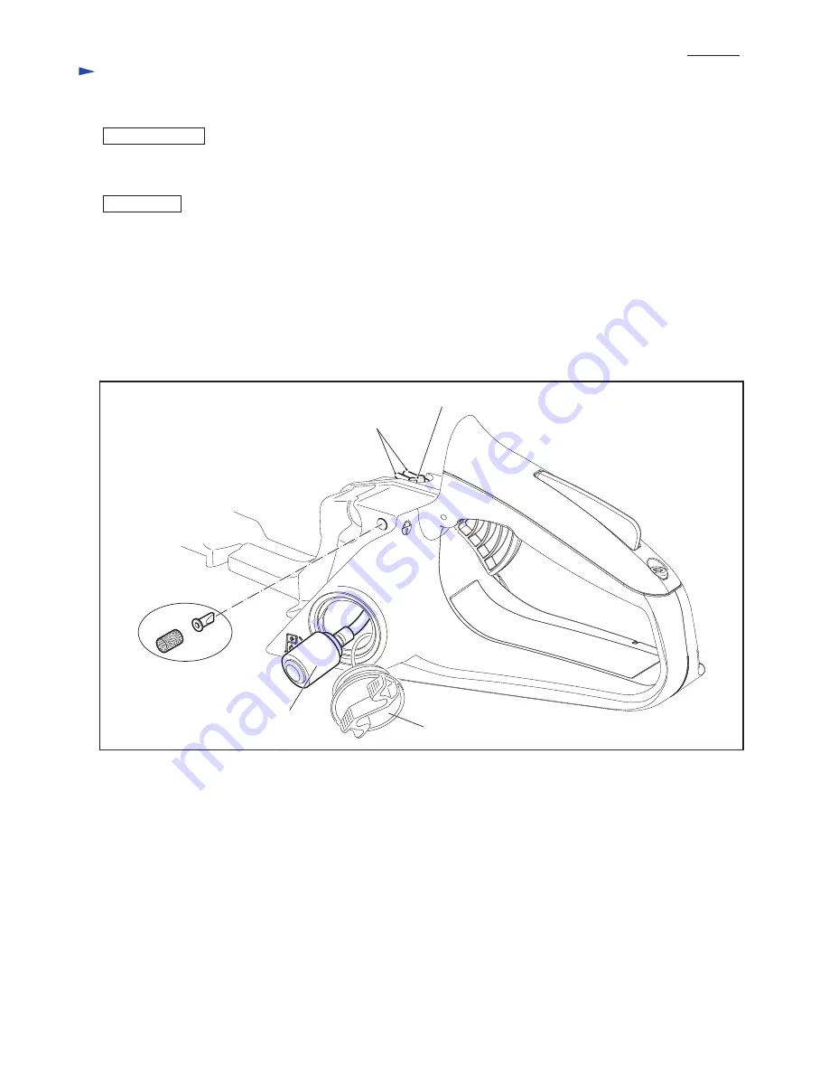
• Pick up Gasoline filter with a bent wire carefully out of Tank. (

Fig. 38

)

   Do not use Pliers because the tips may scratch Fuel line.

   Do not pull Gasoline filter/ Fuel line by force without care because Fuel line may be removed from the intake of Fuel nipple

   inside Tank.

• 

Turn Fuel nipple slightly counterclockwise and then remove it from Tank assembly with small-slotted screwdriver carefully.

Note

: Do not lever Nipple at the ends on the top. They may be broken off.

Ends of Fuel nipple 

(Refer to 

Fig. 26

)

Fuel nipple

Air valve set

Gasoline filter

Tank cap complete

R

epair

DISASSEMBLY

ASSEMBLY

[2] DISASSEMBLY/ ASSEMBLY

[2]-13. Fuel tank

Fig. 38

[2]-14. How to remove Gasoline filter/ Fuel line

Summary of Contents for EA3500S

Page 1: ...Mixed gasoline Mixture ratio of 50 1 JASO FC or ISO EGD Specifications Model Type Dry weight kg lbs Speed at no load min 1 rpm Starting system Yes Rapid start Spring assisted recoil starter Decompres...

Page 2: ...g with 1R223 1R254 when removing assembling Hexalobular tapping screw socket head bolt Torque wrench shaft 20 90N m 1R223 Torque wrench shaft 2 6N m 1R254 adjusting a proper gap between Flywheel and I...

Page 3: ...h drum assembly if chain brake works Fig 5 5 Remove Clutch drum assembly Fig 6 1 Check that the following portions of Clutch drum assembly do not have damage wear Fig 5 Inside Chain sprocket portion N...

Page 4: ...l starter section 9 Remove 4 7x16 Hexalobular tapping screw and Flat washer 5 from Starter complete installation side on Hand guard Fig 8 10 Remove Stop ring E 4 from Pin A of Engine housing complete...

Page 5: ...areful to each direction Note Wear gloves for safety Be careful that Muffler stays very hot for a while after running the engine Fig 10 Repair DISASSEMBLING 2 DISASSEMBLY ASSEMBLY 2 4 Muffler section...

Page 6: ...5 to two Clutch shoes Be careful to the hooking direction of Tension springs 5 When one of Tension spring 5 has a damage replace two Tension springs 5 with the new at the same time Do not replace the...

Page 7: ...ce turn the screw counterclockwise until the pin ends are fit into two slits of Oil pump body If this way is difficult push Piston slightly in the direction of Body Note When set Oil pump complete in...

Page 8: ...ng as follows After making the slack of rope between Starter grip and Reel put the slack into the groove of Reel and pull the starter grip lightly Note Be sure to loosen the spring force before the st...

Page 9: ...washers into two seated holes of Cylinder 2 Pretighten Ignition coil in place by tightening two M5x20 Hexalobular socket head bolts through Isolating washers 3 Insert 1R366 between Ignition coil and...

Page 10: ...ke lever 5 5x16 Hexalobular tapping screw 2 pcs Tube 2 5 112 to Fuel nipple Contact spring 3x10 Tapping screw Grounding wire of Cable harness Tube 2 5 72 removed from Carburetor Guide pin of Engine ho...

Page 11: ...ck Diaphragm assembly metering Refer to Figs 31 and 32 Check that the tip of Valve inlet needle is not worn Replace it the new one if it looks worn Check that Lever metering is not worn and it is asse...

Page 12: ...n of Tank assembly 2 Set Catch lever to the hinge position of Tank assembly Fig 36 Note Torsion spring 10 has to be hooked with Throttle lever as drawn in Fig 37 See Fig 34 and the explanation Assembl...

Page 13: ...ant Supply Soap liquid onto the suspicious surface of Fuel leakage during the pressure test After the above steps reverse the disassembling procedure of DISASSEMBLY of 2 11 Tank assembly Pick up Gasol...

Page 14: ...ide Be sure to use New Gasket Fig 11 and New Crank case sealing When replacing Ball bearing 6201 press fit the inner ring portion to Crank shaft using the same size pipe and a block for placing the co...

Page 15: ...be 0 5 mm Is the gap between Flywheel and Ignition coil 0 25 0 3 mm Is the gap even without any contact wear Is there damage to Insulation of High voltage cable or Ignition cable or coils of Igniton...

Page 16: ...onent of Muffler complete and Cooling plate 266605 8 2 M5x16 Hexalobular socket head bolt 8 1 266606 6 1 M5x40 Hexalobular socket head bolt 8 1 Carburetor 266604 0 2 M4x40 Hexalobular socket head bolt...

Reviews: