P 4/ 11
ASSEMBLING
1
-
5
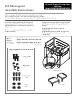
1.
Tighten screws by using DF010D
with Clutch position 10.
2.
Turn Drill chuck clockwise until it seats on the end of the threaded portion
of Spindle.
3.
Fix Hex wrench 10 as shown.
Note:
L-shaped portion of Hex wrench 10 must
be fixed securely.
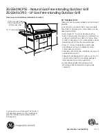
5.
Pull Switch trigger slowly with Drill mode/Speed change 1/Forward
(clockwise) rotation until Spindle is locked.
Note:
Pull Trigger so that Spindle’s rotating reaches full speed in one
second.
6.
Apply adhesive (ThreeBond 1342 (H) or Loctite 243) to threaded portion
when re-using the removed M6x22 Flat head screw.
1
-
6
4.
Housing R must be touched on
the side surface of workbench.
Note:
Battery portion must not
be touched.
Makita Corporation