background image

18

B

Carburetor adjustment is necessary for optimum engine 
performance, for safer and more economical operation. The 
engine should be warm, the air 

Þ

 lter clean, and the chain 

properly tensioned. Have carburetor adjustment done by 
an authorised MAKITA service centre.

The carburetor is factory-adjusted for the air pressure at sea 
level. At other elevations or under other conditions of weather, 
temperature, or humidity, or when breaking in a new engine, it may 
be necessary to make slight adjustments to the carburetor. 

You will need a tachometer 

(

9

, part No. 950 233 210) 

for 

optimum adjustment.

Do not go below the speci

Þ

 ed setting of the main nozzle 

(H). Doing so may cause engine damage due to overheating 
and insuf

Þ

 cient lubrication!

Use the supplied carburetor screwdriver (

8

) for carburetor adjust-

ment. It has a moulded-on projection that aids in adjusting.

Before undertaking the adjustment, run the engine for 3-5 min-
utes to warm it up, but not at high speed!

For proper adjustment, proceed as follows:

 1.

  Basic setting (engine off)


  Start engine and warm up.

 2.

 Set idle

 3.

 Check acceleration


4.

  Check top speed

 5.

  Check idle speed


Repeat steps 2-5 until you get the right idle speed, good 
acceleration and maximum permissible

1. Basic setting


Carefully turn the adjusting screws for the main nozzle (

H

and idle nozzle (

L

) clockwise until you feel a stop.


Turn adjusting screws (

H

) and (

L

turn counter-clock-

wise.

2. Set idle


Set the idle speed per the technical speci

Þ

 cations.


Turning the adjusting screw (

S

) in (clockwise) increases the 

idle speed. Turning it out (counter-clockwise) lowers the idle 
speed. In no case should the chain move.

3. Check acceleration


When the throttle is pressed, the engine should go smoothly 
from idle to high speed. If this is too slow, turn the adjusting 
screw (

L

) in small (max. 

1

/

8

 turns) increments counter-

clockwise.

4.  Check top speed


The basic setting 

H

=

1

 and 

L

=

1

 gives a maximum speed of 

about 13,000 rpm. For higher speed (electronically limited 
to 13,500 rpm), turn the adjusting screw (

H

) a 

maximum


1/4 turn clockwise.The top speed in the governor can be 
clearly heard from the ignition misses. 

 Note: 

Since there 

is an electronic speed governor (limiter) at 13,500 rpm that 
cuts off the ignition current, the top speed cannot be read 
from the tachometer. 

Important: To prevent engine dam-

age, never go below setting (H) 3/4 turns.

5.  Check idle speed


Check the idle speed after setting the top speed (the chain 
must not move).


Repeat the adjustment procedure starting at Step 2, until the 
engine runs with the correct idle speed, good acceleration, 
and top speed.

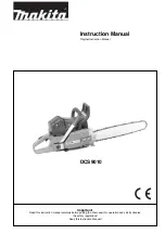
Adjusting the carburetor 

(only for not EU-countries)

L

H

S

8

9

Summary of Contents for DCS 6400

Page 1: ...Read this instruction manual carefully before putting the chain saw into operation and strictly observe the safety regulations Keep this instruction manual DCS6400 DCS6400H DCS6401 DCS6401H DCS7300 DC...

Page 2: ...ing damage Cardboardisabasicrawmaterialandisconsequentlyreuseable or suitable for recycling waste paper recycling Table of contents Page Packing 2 Delivery inventory 3 Symbols 3 SAFETY PRECAUTIONS Gen...

Page 3: ...Symbols You will notice the following symbols on the saw and in the Instruction Manual Read instruction manual and follow the warning and safety precautions Particular care and caution Forbidden Wear...

Page 4: ...t liability for others Never use the chain saw after having consumed alcohol drugs or medication A re extinguisher must be available in the immediate vicinity when working in easily in ammable vegetat...

Page 5: ...g of the chain the rm mounting of the sprocket guard the easy motion of the throttle lever and the function of the throttle lever lock the cleanliness and dryness of the handles and the function of th...

Page 6: ...r over Guide the chain saw in such a way that no part of your body is within the elongated swivelling range of the saw 12 Use the chain saw for sawing wood only Avoid touching the ground with the chai...

Page 7: ...ection of fall and make sure that there are neither people nor objects within a distance of 2 1 2 tree lengths Judging the tree Direction of hanging loose or dry branches height of the tree natural ov...

Page 8: ...tly Regularly clean the chain saw Regularly check the tank cap for tightness Observe the accident prevention instructions issued by trade associations and insurance companies Do not perform any modi c...

Page 9: ...2 when using other oils 50 1 quality grade JASO FC or ISO EGD Chain brake engages manually or in case of kickback Chain speed 2 m s 19 74 20 83 20 83 Sprocket pitch inch 3 8 Number of teeth Z 7 Chain...

Page 10: ...with the chain saw for the following work Put the chain saw on a stable surface and carry out the following steps for mounting the guide bar and saw chain Release the chain brake by pulling the hand g...

Page 11: ...ain Slightly lift the end of the guide bar and turn the chain adjusting screw 13 to the right clockwise until the chain rests against the bottom side of the guide bar While still holding up the tip of...

Page 12: ...A Engaging the chain brake braking If the kickback is strong enough the sudden acceleration of the guide bar combined with the inertia of the hand guard 1 will automatically actuate the chain brake To...

Page 13: ...on of exhaust gases are ensured MAKITA high performance two stroke engine oil is available in the following sizes to suit your individual requirements 1 l order number 980 008 607 100 ml order number...

Page 14: ...ain oil the product guarantee will be null and void Your salesman will inform you about the use of chain oil AVOID SKIN AND EYE CONTACT Mineral oil products degrease your skin If your skin comes in co...

Page 15: ...the saw on a suitable surface C To ensure troublefree operation of the oil pump the oil guide groove at the crank case 2 and the oil inlet bore in the guide bar 3 must be cleaned regularly Note After...

Page 16: ...ot stop immediately when you test the chain brake do NOT use the chain saw Take the chain saw to a MAKITA service center 7 C B Cold starting Pull the choke 1 out until it audibly clicks This simultane...

Page 17: ...adjusting screw H is turned out counterclockwise until it reaches a noticeable stop The limitations do not prevent excessively lean under lu bricated running 1 Start engine and let it warm up 3 5 min...

Page 18: ...sic setting Carefully turn the adjusting screws for the main nozzle H and idle nozzle L clockwise until you feel a stop Turn adjusting screws H and L 1 turn counter clock wise 2 Set idle Set the idle...

Page 19: ...ration At temperatures above 5 C the carburetor must NOT be fed heated air Failure to follow these instructions can lead to damage to the cylinder and piston At temperatures over 5 C place the insert...

Page 20: ...act from the spare parts list All cutters must be of the same length dimension a Cutters with different lengths result in rough running of the chain and can cause cracks in the chain The minimum cutte...

Page 21: ...must be led to the exact same shape as the used teeth including on their running surfaces Always guide the le horizontally 10 to the guide bar E The le holder makes le guidance easier It is marked for...

Page 22: ...he guide plate 5 and brake mechanism cover 7 Use a brush to clean the interior especially the brake band 11 Make sure to leave no residue in the oil guide groove 10 NOTE The brake mechanism cover 7 ho...

Page 23: ...r consult the Extract from the spare parts list Assemble the new sprocket thrust washers and circlip For replacing the guide bar chain and sprocket see PUTTING INTO OPERATION A H NOTE New chains stret...

Page 24: ...aning the lter does not bring an improvement in performance it is time to replace it Cleaning the nylon lter the nylon lter in the lter hood and pre lter Use a soft brush or blow out dirt from the ins...

Page 25: ...universal wrench 7 between the hood and cylinder exactly as shown IMPORTANT Do not stick the wrench in the spark plug hole It should touch only the cylinder otherwise the engine will be damaged With t...

Page 26: ...ghtly until the return spring engages Screw in and tighten screw 5 and washer 6 Guide the cable into the space 4 on the drum and use the cable to turn the drum two turns clockwise Hold the cable drum...

Page 27: ...k plug cap and unscrew the spark plug Press in the starting valve and activate the chain brake Push the cable cutout and ignition cable out sideways Unscrew the two rearmost screws on the cover Unscre...

Page 28: ...pen regulary replace in good time 20 21 Chain brake Have inspected regularly at an authorized service centre Guide bar Turn over to ensure even wear of bearing surfaces Replace in good time 12 23 Star...

Page 29: ...inappropriate repairs Use of unsuitable spare parts or parts which are not original MAKITA parts insofar as they have caused the damage Use of unsuitable or old oil Damage related to conditions arisin...

Page 30: ...protection for 70 cm 4 038 213 602 1 Sprocket guard cpl 5 923 208 004 2 Hexagonal nut M8 6 941 719 131 1 Universal wrench SW 19 13 7 940 827 000 1 Offset screwdriver 8 944 340 001 1 Carburetor screwd...

Page 31: ...ective 2006 42 EG EU EMC Directive 2004 108 EG Outdoor Noise Directive 2000 14 EG The most important standards applied to properly meet the requirements of the above EU Directive were EN 11681 1 CISPR...

Page 32: ...orm 995 707 142 2 11 GB Speci cations subject to change without notice To nd your local distributor please visit www makita outdoor com MAKITA Corporation 3 11 8 Sumiyoshi Cho Anjo Aichi 446 8502 Japa...

Reviews: