P 12/13
C
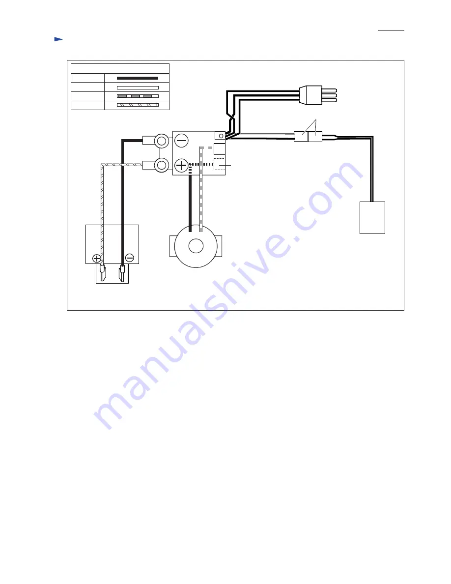
ircuit diagram
Terminal
Switch
Connector
LED
M1
M2 (on the opposite side)
White
Fig. 42
Color index of lead wires' sheath
Black
RedOrange
Endbell complete
FET
Page 1: ...countries except North America Battery Specification Net weight 2 kg lbs Capacity Ah Cell Voltage V 18 No load speed strokes per min Steel Capacities mm Wood 1 10 3 8 Aluminum 20 25 32 135 5 5 16 2 8...
Page 2: ...Crank complete Balance plate Push plate Gear housing complete Push pin Whole surface Surface that contacts Gear housing cover complete Surface that contacts Retainer Upper middle and lower portions of...
Page 3: ...ig 4 2 Set the end of Torsion spring 6 in place by turning clockwise viewed from the side of Base with a small slotted screwdriver or the like Fig 5 Tool opener Torsion spring 6 Pan head screw M4 Fig...
Page 4: ...complete Motor housing R Motor housing L Gear housing cover section Gear housing cover section side Handle R Handle L Motor housing L Fig 6A Motor housing R A Tapping screws that fasten Handle R to Ha...
Page 5: ...n of the arrow 2 Pull down Rod until it stops 4 Pull off Rod from Gear housing cover complete 5 By unscrewing four M4x10 Pan head screws Gear housing cover section can be disassembled as illustrated b...
Page 6: ...rough Linear guides to Gear housing cover complete with two M4x10 Pan head screws then fasten Linear guides to Gear housing cover complete with the other two M4x10 Pan head screws Fig 17 8 Assemble St...
Page 7: ...te Be careful not to lose Push pin Fig 20 Fig 21 Dust cover DISASSEMBLING Crank complete Needle bearing 407 groove portion of Slider Gear housing complete Gear housing cover complete Gear housing cove...
Page 8: ...ousing complete Fig 27 2 Assemble Seal plate on Push plate Mount Push plate on Gear complete then assemble Gear complete to the shaft portion of Gear housing complete Fig 28 3 Lubricate the parts with...
Page 9: ...Note 1 Do not forget to apply threadlocker to the two bolts 2 The recommended fastening torque is 2 4 3 5 N m 7 Assemble Retaining ring S 18 to the shaft portion of Gear housing complete using 1R291...
Page 10: ...Tapping screw 4x30 4 pcs Motor section Fig 34 Fig 35 Motor housing R Armature Yoke unit Endbell complete Tapping screw 4x18 4 pcs DISASSEMBLING assembly of reciprocating mechanism Motor housing L Do...
Page 11: ...pring 3 and Cap 5 can now be removed from Lever 17 Compression spring 3 Cap 5 Wrong Correct Gear housing complete The two projections of Switch serves as the guide for Switch lever Switch Switch lever...
Page 12: ...P 12 13 Circuit diagram Terminal Switch Connector LED M1 M2 on the opposite side White Fig 42 Color index of lead wires sheath Black Red Orange Endbell complete FET...
Page 13: ...ure to fix with Lead wire holder A 4 Lead wire of Switch orange Connect this lead wire to plus pole of Terminal Note Be sure to fix with Lead wire holder A 5 Lead wire of Light circuit Route between t...