P 1
3
/ 1
4
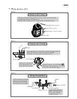
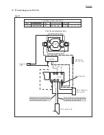
Name plate
Field lead wire (black)
Field lead wire (black) and Brush holder’s lead wire (orange) are guided out through
the right bottom opening of Name plate side.
Brush holder’s lead wire (orange)
Fig. D-8
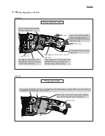
Fig. D-9
W
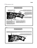
iring diagram for 9237CB
Wiring from Motor housing set
5
4
3
Connect the receptacles of Controller’s lead wires to Switch terminals
so that Lead wires come to the reverse side of Lock button.
And tilt the connected receptacles as drawn left.
Lock button
Wiring to Switch’s Terminals
1
Receptacle covered with tube
has to be connected to the
terminal on Lock button side.
Connect Receptacles to Switch terminals 1
while facing the connecting area of Lead wires
to the reverse side of Switch trigger.
Switch trigger


