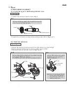
Strain relief
Rib
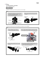
Connector 2-SD
Fig. D-10
Fig. D-11
15 mm
Choke coil
Noise suppressor (with two Lead wires)
Strain relief
Pin
P 1
4
/ 1
4
W
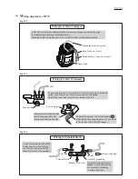
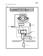
iring diagram for 9237CB
Wiring under Switch
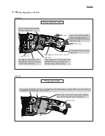
Wiring in Handle set (R)
Noise suppressor (with two lead wires)
and Choke coil are put to the place
as drawn above if they are used.
Route Lead wires under Switch and decentralize
them with the ribs and pins of Housing R.
Noise suppressor’s lead wires ( 2 pcs.) must be beyond Switch trigger by routing between the ribs and the pin
of Handle set R near the upper side of Switch.
Come out at least 15 mm long
of Power supply cord from
Strain relief, and clamp the cord
with Strain relief.
Be careful not to put Lead wires
on these ribs.
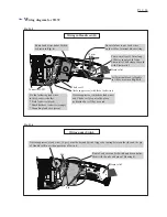
Route Lead wires under Switch
as drawn in
Fig. 11.
Fix Field lead wire (black) and
Brush holder’s lead wire (orange)
in this Lead wire holder.


